MegOhmMeter
Operating the Meter
9
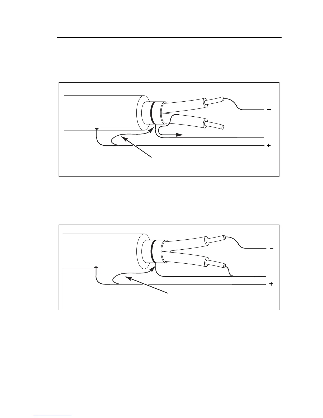
Figure 6 shows how to prevent surface current leakage by connecting a lead
from the Guard terminal to a conductor wrapped around the inner insulation.
The surface leakage current is directed to the Guard terminal. This removes the
leakage current from the measurement path between the positive and negative
terminals, and improves the accuracy of the test readings.
Leakage
Current
G
Shield
( )
( )
( )
Optional
ASW14F.EPS
Figure 6. Guard Terminal Connection
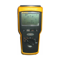
Figure 7 shows how to improve the measurement setup by connecting the
Guard terminal to the unused wire and coupling it to the inner insulation. This
insures that the Meter measures the leakage between the selected conductor
and the outer shield, but eliminates the leakage path between conductors.
Leakage
Current
G
Shield
( )
( )
( )
ASW15F.EPS
Figure 7. Improved Guard Terminal Connection