1732/1734/1736/1738/3540 FC
Calibration Manual
8
Example:
Measurement at 120 V/16 A using an iFlex1500-12 in low range. Power Factor is 0.8.
Active power uncertainty :
The uncertainty in W is
Apparent power uncertainty :
The uncertainty in VA is
Reactive/non-active power uncertainty :
In case of a measured voltage that is >250 V, the additional error is calculated with:
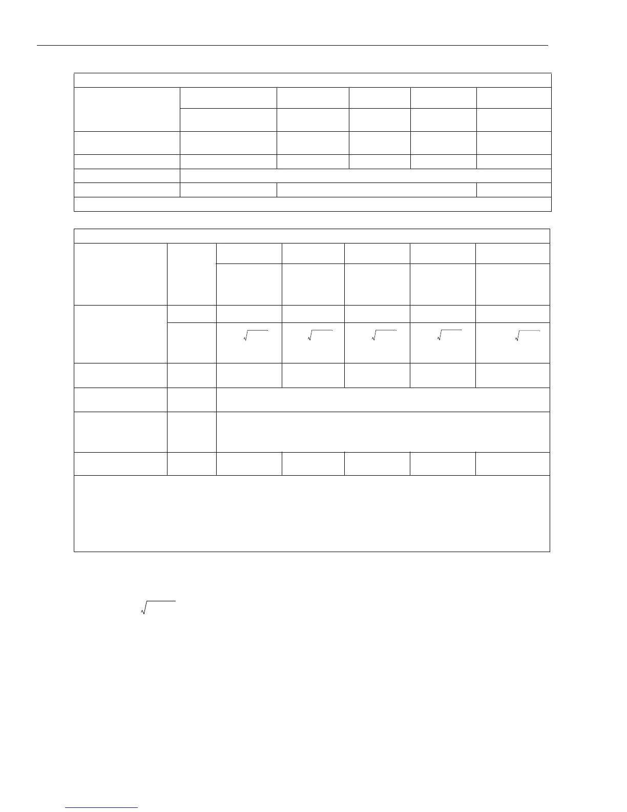
Power/Energy
Parameter
Direct Input
[1]
iFlex1500-12 iFlex3000-24 iFlex6000-36 i40S-EL
Clamp: 50 mV/500 mV
Rogowski: 15 mV/150 mV
150 A/1500 A 300 A/3000 A 600/6000 A 4 A/40 A
Power Range W, VA, var
Clamp: 50 W/500 W
Rogowski: 15 W/150 W
150 kW/1.5 MW 300 kW/3 MW 600 kW/6 MW 4 kW/40 kW
Max. Resolution W, VA, var 0.1 W 0.01 kW/0.10 kW 1 kW/10 kW 1 kW/10 kW 1 W/10 W
Max. Resolution PF, DPF 0.01
Phase (Voltage to Current)
[1]
±0.2 ° ±0.28 ° ±1 °
[1] Only for calibration laboratories
Intrinsic Uncertainty ±(% of measurement value + % of power range)
Parameter
Influence
Quantity
Direct Input
[1]
iFlex1500-12 iFlex3000-24 iFlex6000-36 i40S-EL
Clamp:
50 mV/500 mV
Rogowski:
15 mV/150 mV
150 A/1500 A 300 A/3000 A 600/6000 A 4 A/40 A
Active Power P
Active Energy E
a
PF ≥0.99
0.5 % + 0.005 % 1.2 % + 0.005 % 1.2 % + 0.0075 % 1.7 % + 0.0075 % 1.2 % + 0.005 %
0.1
≤PF
<0.99
% + 0.005 %
% + 0.005 % % + 0.0075 %
% + 0.0075 %
% + 0.005 %
Apparent Power S
Apparent Energy E
ap
0 ≤PF ≤1
0.5 % + 0.005 % 1.2 % + 0.005 % 1.2 % + 0.0075 % 1.7 % + 0.0075 % 1.2 % + 0.005 %
Reactive Power Q
Reactive Energy E
r
0 ≤PF ≤1
2.5 % of measured apparent power/energy
Power Factor PF
Displacement Power
Factor
DPF/cosφ
-
Reading ± 0.025
Additional uncertainty
(% of power high-range)
V
P-N
>250 V 0.015 % 0.015 % 0.0225 % 0.0225 % 0.015 %
[1] Only for calibration laboratories
Reference Conditions:
Environmental: 23 °C ±5 °C, instrument operating for at least 30 minutes, no external electrical/magnetic field, RH <65 %
Input conditions: CosΦ/PF=1, Sinusoidal signal f=50/60 Hz, power supply 120 V/230 V ±10 %.
Current and power specifications: Input voltage 1 ph: 120 V/230 V or 3 ph wye/delta: 230 V/400 V
Input current >10 % of current range
Primary conductor of clamps or Rogowski coil in center position
Temperature Coefficient: Add 0.1 x specified accuracy for each degree C above 28 °C or below 18 °C
0.5
1 PF
2
–
3 PF×
------------------------
+
1.2
1 PF
2
–
2 PF×
------------------------
+
1.2
1 PF
2
–
2 PF×
------------------------
+
1.7
1 PF
2
–
2 PF×
------------------------
+
1.2 1.7
1 PF
2
–
PF
------------------------
×+
σ
ρ
±1.2
10.8
2
–
20.8×
-----------------------
+
0.005% P
Range
×+
± 1.575 % 0.005 % 1000 V 150 A××+()± 1.575 % 7.5 W+()===
± 1.575 % 120 V 16 A 0.8× 7.5 W+××()±31.7 W=
σ
s
± 1.2 % 0.005 % S
Range
×+()± 1.2 % 0.005 % 1000 V 150 A××+()± 1.2 % 7.5 VA+()== =
± 1.2 % 120 V 16 A 7.5 VA+××()±30.54 VA=
σ
Q
±2.5 % S×()± 2.5 % 120 V× 16 A×()±48 var== =
Adder 0.015 % S
High Range
× 0.015 % 1000 V× 1500 A× 225
W/VA/var
== =

 Loading...