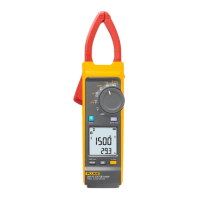
CAT III 1500V TRMS Clamp Meter
Calibration Adjustment
19
mV DC Adjustment Procedure
See Table 7 for only the mV dc adjustment steps. When the Product shows SAUE on the
LCD, calibration is complete.
Resistance/Capacitance Adjustment Procedure
See Table 8 for both the Resistance/Capacitance adjustment steps. When the Product
shows SAUE on the LCD, calibration is complete.
Table 7. mV DC Adjustment
Step Display Calibrator Output Operation
1.
C-08 STBY Push I
2.
C-09 STBY Push I
3.
C-10 0 V
Push
4.
C-11 0.5 V
Push
5.
C-08 STBY Push e
6.
Save --- ---
Table 8. Resistance/Capacitance Adjustment
Step Display Calibrator Output Operation
1.
C-12 0 Ω
Push
2.
C-13 600 Ω
Push
3.
C-14 660 Ω
Push
4.
C-15 6000 Ω
Push
5.
C-16 6600 Ω
Push
6.
C-17 60 000 Ω
Push
7.
C-18 0.1 μF
Push
8.
C-19 0.5 μF
Push
9.
C-20 1.5 μF
Push
10.
C-21 110 μF
Push
11.
C-22 500 μF
Push
12.
C-23 1000 μF
Push
13.
C-12 STBY Push e
14.
Save --- ---

 Loading...