Pressure Calibrator with Electric Pump
Getting Acquainted with the Calibrator
5
Getting Acquainted with the Calibrator
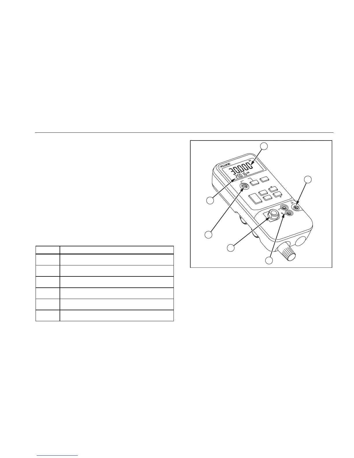
The Calibrator displays pressure and current
measurements simultaneously. See Table 2 and Figure 2
for front panel features.
The upper display shows the applied pressure or vacuum
(shown as a negative value). Press ENTER then UNITS
to select a different unit. When the power is cycled off and
on, the Calibrator retains the unit last selected.
The lower section of the display shows the current (up to
24 mA) applied to the current (mA) inputs, or the mA
output value.
To source loop voltage, press Z while pressing O ON.
Pushbutton operation is described in Table 3. Pump
features are shown in Figure 3 and described in Table 4.
Table 2. Front Panel Features
Item Feature
A Pressure Measurement
B Pressure Module Input
C Current Terminals
D Pressure Sensor Input (install filter here)
E Power Button
F Current mA Measurement and Source
34.5
-7
719
PRESSURE
CALIBRATOR
HOLD
mA
OUTPUT
25% Step
COM
30V
MAX
SOURCE/SIMULATE
0-24 mA
UNITS
LIMITS
ENTER
LOOP
POWER
ADJUST ALL.
PUMP
mA
MIN
MAX
HOLD
SWITCH
TEST
ZERO
1
2
3
4
5
6
Fgx005f.eps
Figure 2. Front Panel Features

 Loading...