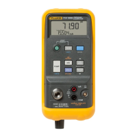
Pressure Calibrator with Electric Pump
Pump Valve Assembly Cleaning Instructions
15
Pump Valve Assembly Cleaning
Instructions
1. Using a small screwdriver, remove the two valve
retention caps located in the oval shaped opening on
the underside of the Calibrator.
2. After the caps have been removed, gently remove the
spring and o-ring assembly.
3. Set aside the valve assemblies in a safe area and
clean out the valve body using a cotton swab soaked
in IPA (isopropyl alcohol).
4. Repeat this process several times using a new cotton
swab each time until there is no remaining sign of
residue.
5. Run pump for a few seconds.
6. Clean the o-ring assembly and o-ring on the retention
caps with IPA and inspect the o-rings closely for any
cuts, nicks, or wear. Replace if needed.
7. Inspect the springs for wear or loss of tension. They
should be approximately 8.6 mm long in the relaxed
state. If they are shorter than this, they may not allow
the o-ring to seat properly. Replace if needed.
8. Once all parts have been cleaned and inspected,
reinstall the o-ring and spring assemblies into the
valve body.
9. Reinstall the retention caps and gently tighten the
cap.
10. Seal the output of the Calibrator and pump up the unit
to at least 50 % its rated pressure.
11. Release the pressure and repeat several times to
ensure that the o-rings seat properly.
The Calibrator is now ready for use.
Using an External Pump
W Caution
To avoid damage to the Calibrator and
possible release of pressure, do not connect
the internal sensor to an external pressure
source that exceeds the maximum rated
pressure.
To develop higher pressure or vacuum, use an external
pump (such as the Fluke Model 700PTP). Use a Fluke
Pressure Module connected to the pressure module input
on the Calibrator. Pressure modules are listed in Table 5.
Make overall connections as shown in Figure 6.
Refer to setup and operating instructions included with the
pressure module and pump.

 Loading...