719 Series
Users Manual
18
Supplying Loop Power
The Calibrator can supply loop power at 24 V dc to a
current transmitter that is disconnected from the system.
Use the following procedure:
1. With power off, hold down Z while pressing n.
Loop Power appears in the display.
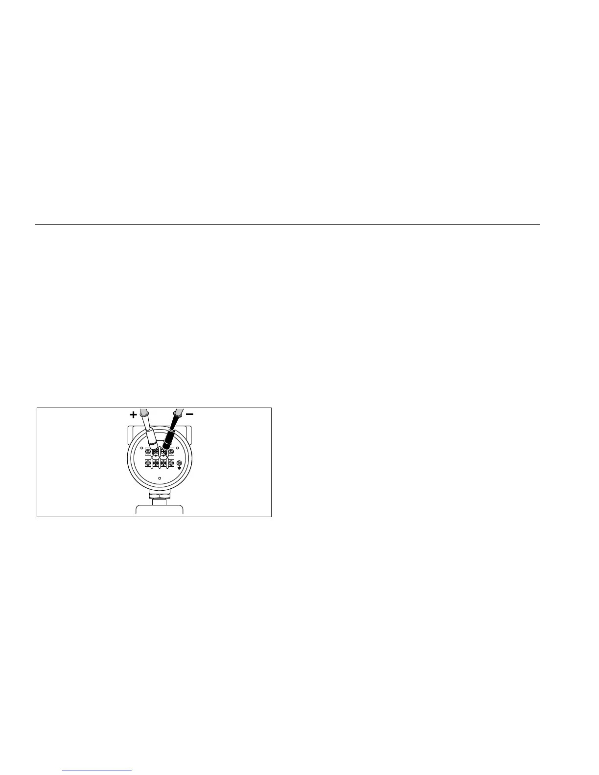
2. With the transmitter disconnected from normal loop
power, connect the Calibrator mA (+) and COM (-)
test leads in series with the instrument current loop as
shown in Figure 7.
3. Measure loop current in the mA display.
4. Press n off to deactivate the 24 V dc supply when
finished sourcing loop voltage.
SIGNAL
TEST
+
–
qo007f.eps
Figure 7. Sourcing Loop Voltage
mA Modes
Different mA functions can be accessed by repeatedly
pressing A:
• mA- measured current is displayed.
• Percent Mode- current is displayed as a percentage
based on a 4-20 mA scale.
• Percent Error Mode- transmitter current output error
is displayed. Error is calculated based on a
configurable zero and span pressure and a 4-20 mA
scale.
• mA Source- Outputs current displayed. Use Vor U to
adjust current setting.
• mA Simulate- Sets current when using an external
24 V loop power supply. Use Vor U to adjust the
current setting.
Note
Display flashes OL if there is an open circuit in
source or simulate mode.

 Loading...