13
The icons represent the connected devices:
The NetTool icon
is located in the center of
the diagram. Select this icon to access the tester’s
configuration screens.
The Network
and PC
icons appear to the
left or right of the NetTool icon, depending on
how you connected the cable. You can select
these icons to drill down and obtain detailed
information about the device and/or network.
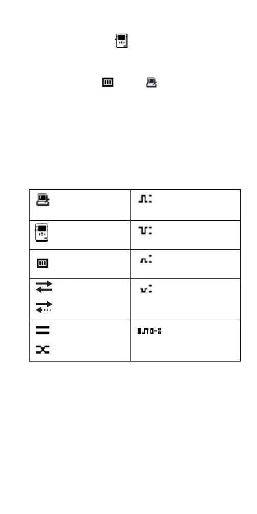
The network symbols provide link and cabling
information, as described in the following table.
Legend for the Network Diagram
Connected device
(PC, printer, IP phone)
Normal level, normal
polarity
NetTool tester
Normal level, reverse
polarity
Network
Low level, normal
polarity
Full duplex
Half duplex
Low level, reverse
polarity.
Straight cable
Crossed cable
Automatic
MDI-X connection
 Loading...