14
주의:
IN 포트와 OUT 포트를 반대로 삽입하지 마십시오. 그럴 시에는 조종기가 각 원격 모듈과 이를 따르는 원격 모듈들을
구분할 수 없습니다.
http://www.flysky-cn.com
Notice:
Don't make IN port and OUT port oppositely, or it will cause that the transmitter can't distinguish each
telemetry module and its following telemetry module(s).
FS-CVT01:외부 전압 연결
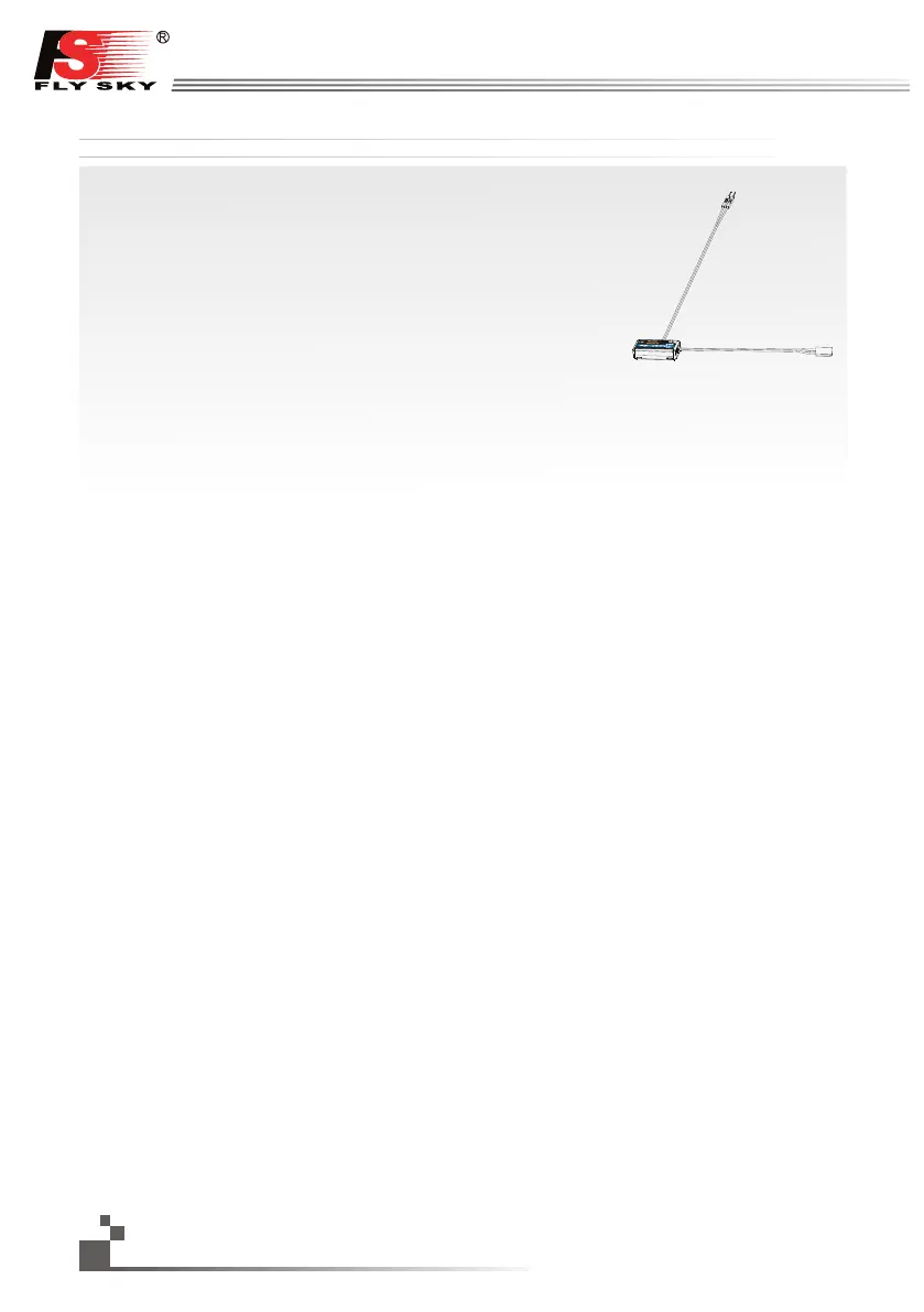
1. Standard 3 Pin의 한 쪽은 외부 전압 모듈의 “OUT” 포트에 꽂으시고 다른 한 쪽은 수신기의
“IN” 포트 또는 다른 센서들의 “IN” 포트에 그림과 같이 꽂으십시오.
2. 송신기와 수신기의 전원을 켜십시오. 수신기의 화면에 “출력전압4:12.40V”가 표시될 것인데,
이는 성공적인 설치를 뜻합니다.
3. 배터리 포트에 빨강색 접촉 핀과 검정색 접촉 핀을 각각 적합한 곳에 연결시키십시오. 빨강색은
양극이고 검정색은 음극입니다. 수신기의 화면에 “Ext.voltage4:12.4v”가 표시될 것인데,
이는 시험된 전압은 12.4v임을 뜻합니다.
주의: 빨간 선과 검정색 선의 극성은 바뀔 수 없습니다. 수신기가 손상될 수 있습니다.
FS-CVT01: External voltage connectiontelemetry
Operation instruction:
1. Insert one end of standard 3 PIN plug into “OUT” port of external voltage module, and insert the other end
into “IN” port of receiver or other sensor, as picture above.
2. Switch on transmitter and receiver. “Ext.voltage4:12.40V” will be shown in receiver window in display screen,
which means the installation is successful.
3. Insert red and black contact pin into battery port respectively. The red one is positive pole and the black one
is negative pole. As shown: “Ext.voltage4:12.4v” is shown in the receive widow in display screen, which
means the tested voltage is 12.4v
Attention: the polarity of red and black line can not be reversed, or the receiver will be damaged.
 Loading...