FS-CEV01 i-BUS serial bus receiver connection
버스수신기는직렬에서4 모듈을최대18 채널과연결할수있습니다.K1버튼과K2는각각C 1과C2에반응합니다.
1、 FS-CEV01 수신기의 “IN” 포트는 수신기의 “OUT” 포트에 반응합니다.
2、FS-CEV01 수신기의 “OUT” 포트는 FS-CEV01 수신기를 연결하는데 사용됩니다.
3、수신기에 버스 수신기를 삽입 한 다음 일치하는 송신기와 수신기의 전원을 켭니다. LED는 켜져 있을 것입니다
4、 서보 설정의 기능에 들어가기 위해 수신기 설정의 메인 메뉴를 선택하십시오.
5、확장되어야 하는 채널을 선택하십시오. 이 때, 버스 수신기의 LED가 꺼져있어야 합니다
6、해당 채널을 이와 동일한 라인의 플라스틱 바늘로 누르십시오. 설정을 성공
했을 시에는, LED가 자동적으로 번쩍일 것입니다.
7、확인하기 위해 서보를 삽입하십시오.
8、위 지침대로 버스 수신기의 4채널을 설정하십시오.
9、더 많은 채널들이 필요하면 “OUT” 포트의 First Stage 버스 수신기를
갖고 있는 새로운 버스 수신기를 연결시키십시오. 위의 지침대로 새로운
것을 설정하십시오.
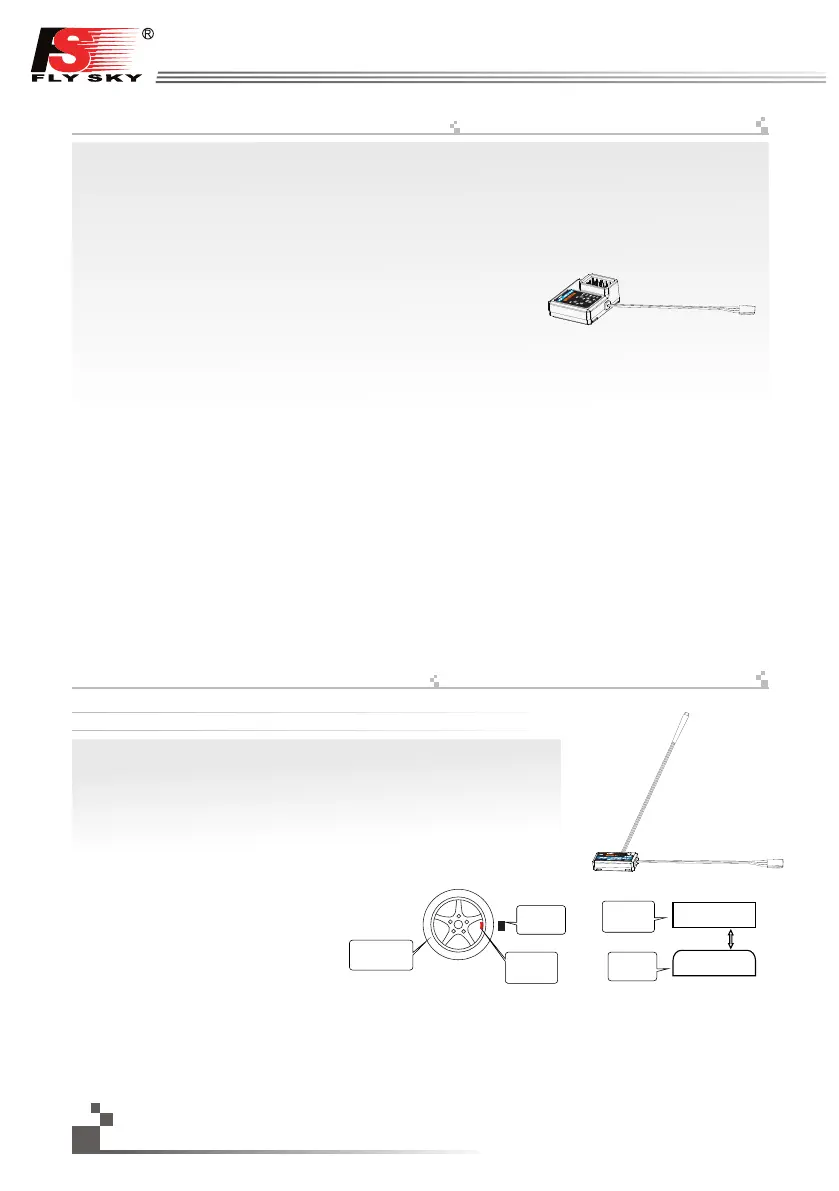
Data telemetry connection
데이터 운행 방법 FS-CPD01: 회전 속도 모듈
1. Stand ard 3 P in의 한 쪽은 Sp e ed Acqu isition 모듈의 OUT 포트 에 꽂으 시 고,
다른 한 쪽은 수신기 또는 다른 센서의 IN 포트에 그 림과 같 이 꽂으십 시오.
2. 예를 들어: 모델의 내부 허브에서, 센 서와 자석 사이의 거 리는 2m m 이하입니다.
자석의 북극이나 남극은 센서와 평 행 을 이뤄 야 합니 다.
3. 송신기와 수신기의 전 원을 켜 십시오. 수신기의 화면에 모터 속도 회전 수가
표시될 것입니다. 바퀴의 움직임에 따라 속도의 값이 변하는데, 이는 성공적인
설치를 뜻합니다.
http://www.flysky-cn.com
12
FS-CEV01 i-BUS 직렬 버스 수신기 연결 단계
Serial bus receiver can connect 4 modules with 18 channels in serial at most. Button K1 and K2 correspond to
C1 and C2 respectively.
Operation:
1. “IN” port of FS-CEV01 receiver corresponds to “Out” port of receiver.
2. The “OUT” port of FS-CEVO1 receiver is used to connect post level FS-CEV01 receiver。
3. Insert the bus receiver to receiver, and then switch on the matched transmitter and receiver. The LED will
be on.
4. Select main menu of receiver setup to enter the interface of servo setup.
5. Select channel which need to be expanded, meanwhile LED of bus receiver is off.
6. Push relevant channel button by plastic needle of matching line. The setup is successful if LED flashes
automatically.
7. Insert servo to check.
8. Set up 4 channels of bus receiver as above steps.
9. Just connect a new bus receiver with “OUT” port of first stage bus receiver if more channel needed. Set up
the new one as above steps.
Notice:
when the load of serial bus receiver is excessive and electric current is higher than usual, please supply
power directly to the serial bus receiver or it will break cables.
Data operation instruction telemetry
FS-CPD01: revolving speed module.
Operation:
1. Insert one end of standard 3 PIN plug into “OUT” port of speed acquisition
module, and insert the other end into “IN” port of receiver or other sensor,
as picture above.
2. Forexample:Insidehub of the model, the distance between sensor and magnet is less than2mm. The north
Pole or the south pole of themagnet has to be paralleled with sensor.
3. Switch on transmitter and receiver. “Motor speed 2:0RPM” will be shown in receiver window in display screen.
Speed value changes as turning wheel, which means installation is successful.
magnet
주의: 직렬 버스 수신기가 부하로 평상시보다 전류가 높으면, 직렬 버스 수신기에 직접적으로 전력을 공급하십시오.
그렇게 하지 않으시면 케이블이 끊어질 것입니다
Sensor
Car wheel
N
S
Sensor
<2mm
바퀴
자석
센서
자석
센서
Magnet
 Loading...