18. TRANSMITTER
18.1 CONNECTION DESCRIPTION
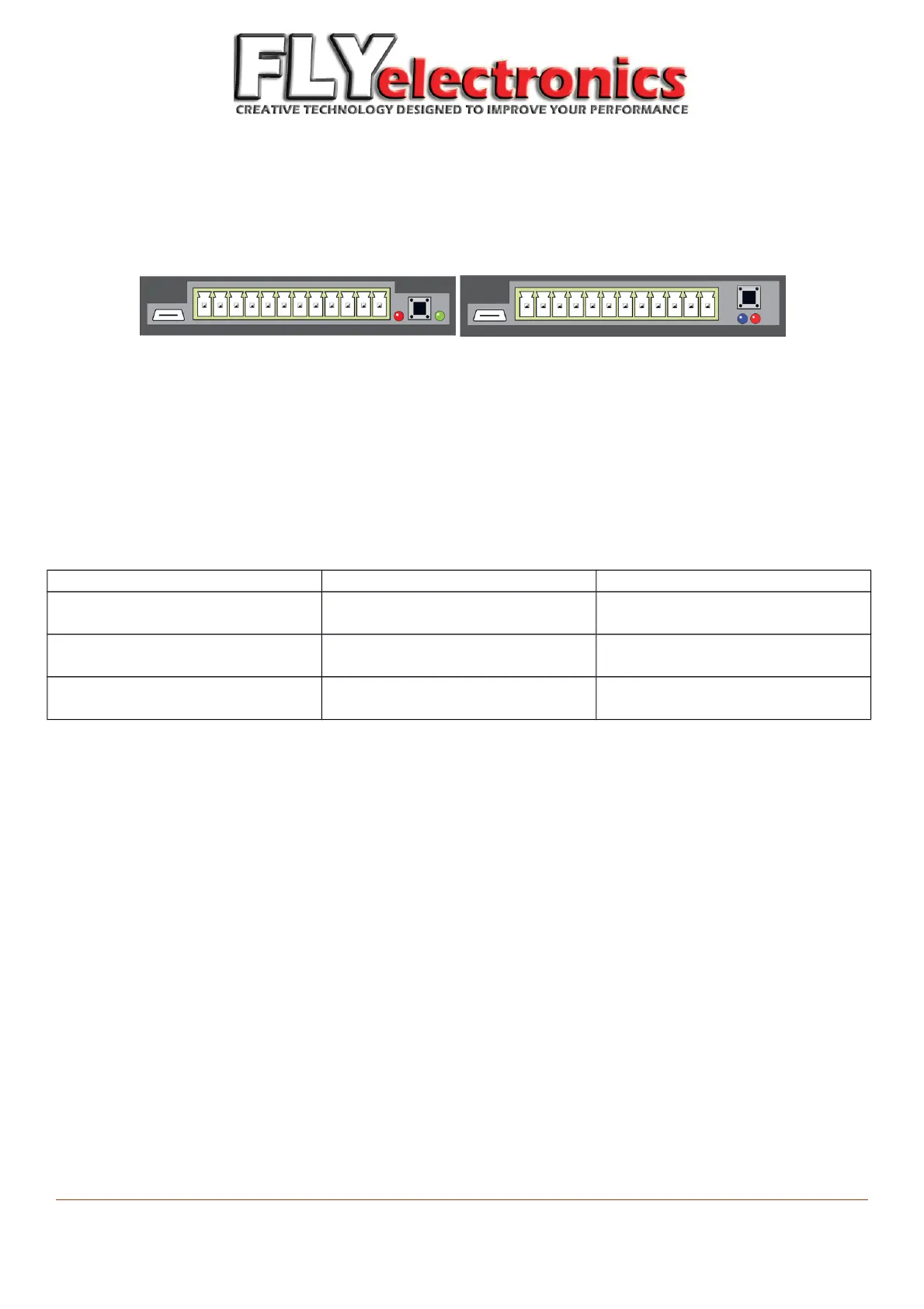
Transmitter 1.0 Transmitter 1.1
Elements seen above (from left to right):
- microUSB plug to charge the connector Li-Ion battery,
- plugs to connect peripherals and sensors,
- switch/pairing button – device will automatically turn on when RPM are detected. If you want to turn it on while
motor is off – use this button,
- information diodes
LED behavior:
Transmitter 1.0 Transmitter 1.1
Red diode Short flashes – charging (while
device is on)
Short flashes – connecting with
receiver
Green diode Short flashes – connecting with
receiver
Not available
Blue diode Not available Short flashes – charging (while
device is on)
Both LEDs turned on is a sign of breakdown on the wire.
Should this ever happen – in case of version 1.0 you have to wait until battery wears off. If you have version 1.1, you
can restart it by pressing restart button – in the rear left corner of the transmitter ( by USB plug).
Charging can also be performed when device is turned off.
The transmitter should be mounted – connector to ground.
FLYelectronics All Rights Reserved Page 23