7
Supply voltage 24 V AC ±10 % 50 – 60 Hz
Power consumption Max 5 VA
Dimensions mm (in) (W × H x D) 150×70×112 (5.9×2.75×4.4)
Temperature range 0°C – + 50°C (32°F–122°F). Max 80% RH
Channel A
Voltage to detector 12 V DC
Alarm I > 20 mA
Output alarm Solid state relay 24 V AC, 100 mA
Channel B
Voltage to detector 12 V DC
Alarm I > 20 mA
( I < 20 mA if RUN is activated)
Output alarm Solid state relay 24 V AC, 100 mA
Channel C
Alarm R Ω 3kΩΩ
Output alarm Solid state relay 24 V AC, 100 mA
Reset Manual when R < 900 Ω
Channel D
Alarm R > Rset
Output alarm Solid state relay 24 V AC, 100 mA
Output Max. load approx. 250 Ω
0 – 20 mA range 50°C – 150°C
(122°F–302°F) (0,2 mA/°C ±2,5 %)
ΣΣ
ΣΣ
Σ-alarm
Alarm Activated by alarm from each
individual channel
Output alarm Solid state relay 24 V AC, 100 mA
Interlock
Alarm Activated by alarm and supply failures
Function Normally closed
Breaking capacity 240 V 4 A vid cos
ϕ
= 1
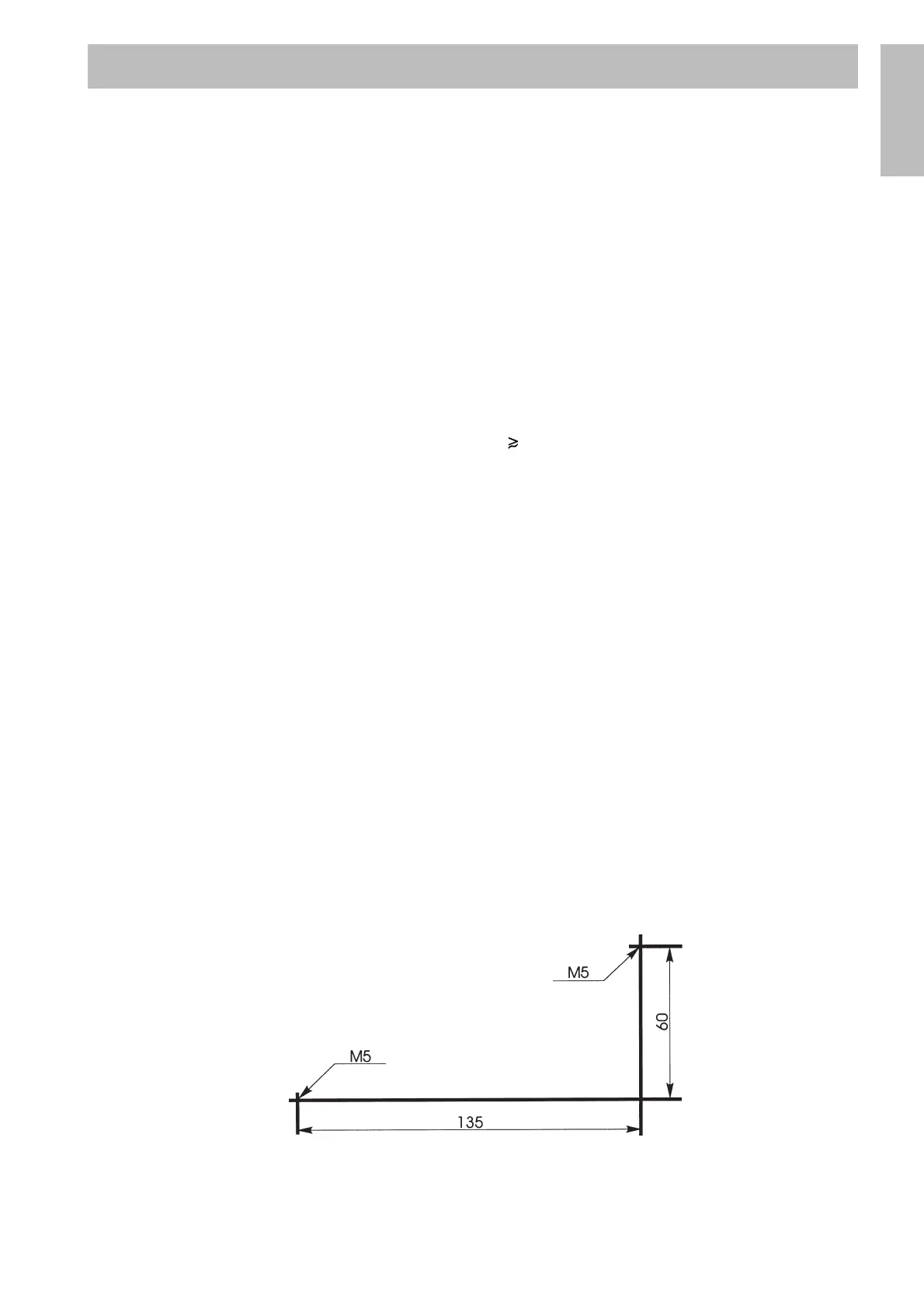
Drilling instruction
TECHNICAL DATA
English