8
FAULT TRACING (TROUBLE SHOOTING)
With the aid of a multimeter and a couple of resistors,
it is possible to check from the outside whether the
unit is functioning properly. The multimeter shall have
an internal resistance of at least 20 kΩ/volt.
In order for the monitoring unit to function properly,
the supply voltage must lie within the specified limits,
i e 24 V AC ±10 %.
It is important to check the value of the resistors
before using them to check the D-channel. All
functions shall be tested during fault tracing. If any
function is not right, contact your ITT Flygt service
shop.
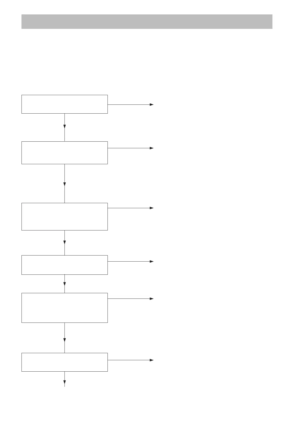
Supply voltage
No
Is pilot lamp 61 lit ? Check that supply current is
correctly connected.
Yes
No
Connect the multimeter to Investigate possible faults in the
terminals 14 and 16. power supply.
Is the voltage 21.6 – 26.4 V AC?
Yes
Channel A
No
Connect the multimeter to Check the supply voltage.
terminals 17 and 18. Contact an ITT Flygt service shop.
(NOTE! Correct polarity ±.)
Is the voltage 10.8 – 12 V DC?
Yes
No
Disconnect the leakage sensor. Contact an ITT Flygt service shop.
Does pilot lamp 51 light ?
Yes
No
Connect the resistor, 330 Ω Contact an ITT Flygt service shop.
1/2 watt (or reference sensor)
between terminals 17 and 18.
Does the pilot lamp 51 go out ?
Yes
No
Is A-alarm activated after Contact an ITT Flygt service shop.
about 5 seconds ?
Yes