EPE2-Controller for Meter Draining System
EPE2
Installation Manual
Sening®
Innovative Tank Truck Systems
10 Rev. 1.03 / JS / jp / March 2010 MN F08 003 US / DOK-450E
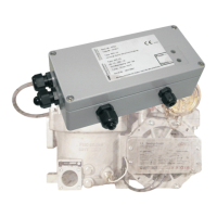
1.4.1 “MultiFlow residue discharge“ function
Alternatively for control the type approved MultiFlow electronic meter in connection with the
EPE2-Controller can be used. The wiring is made as per the electric circuit diagram drawing
no. E61.351994 / page 44.
The EPE2-Controller is connected via a data bus directly with the MultiFlow electronic meter
[12]. The electronic MultiFlow meter takes over all control functions as per the EPE2. Hence
the 3/2-way solenoid valve [21] of the switching devices is no longer needed.
If the type approved MultiFlow electronic meter together with the EPE2-Controller is used for
control, the 3/2-way solenoid valve [21] for the electric switching device is no longer needed.
For the supply of residual discharge components with compressed air, can be used a sole-
noid valve [22] (DN8 / actuator spring-to-open) or an optional manually operated ball valve.