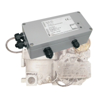
EPE2-Controller for Meter Draining System
EPE2
Installation Manual
Sening®
Innovative Tank Truck Systems
14 Rev. 1.03 / JS / jp / March 2010 MN F08 003 US / DOK-450E
3.1.1 Operating modes
The EPE2-Controller are designed for two operating modes.
•
In both operating modes the residue discharge switch or sensor is connected with the sensor
input J3 on the REC-1S control board.
(see also drawing no. 61.351684 / page 43 and 61.351994 / page 44)
•
The sensor or switch type has to be adjusted as described in paragraph 3.4 / page 16.
3.1.1.1 “Stand-Alone residue discharge“ mode
REC-1S printed circuit board DIP switch S1-1: OFF
•
In this operating mode there are 2 switching outputs available.
•
The switching output “2“ controls the solenoid valve in the main air feed.
•
The “Power Out“ switching output, switches the supply voltage for the flow computer meter
electronics.
•
The flow chart of the residue discharge and an exact functional description can be found in
chapter 0 / page 19.
CAN Bus termination resistors
SVC-2S printed circuit board DIP switch S1-1: OFF (termination resistors ON)
•
The switch has no effect on function in this operating mode. The selected switch setting is
thus arbitrary.
3.1.1.2 “MultiFlow residue discharge“ mode
REC-1S printed circuit board DIP switch S1-1: ON
•
In this operating mode control of the main air is made via the Sening
TM
MultiFlow. The meter
electronics needs not to be switched separately.
•
The “Power Out“ switching output is not switched in this operating mode and can thus be
used optionally otherwise.
•
In this case the DIP switch S1-2 on the power supply printed circuit board SVC-2S is to be
set to the “ON“ position.
CAN Bus termination resistors
If the EPE2-Controller is used together with the MultiFlow in a CAN Bus network and operated as
the last device on the Bus, then the termination resistors are to be switched ON.
SVC-2S printed circuit board DIP switch S1-1: OFF (termination resistors ON)
•
To activate the termination resistors the DIP switch S1-1 on the power supply board SVC-2S
is to be placed in the “OFF“ position.
•
This is only necessary when the EPE2-Controller is the last device in a CAN Bus network !