EPE2-Controller for Meter Draining System
EPE2
Installation Manual
Sening®
Innovative Tank Truck Systems
40 Rev. 1.03 / JS / jp / March 2010 MN F08 003 US / DOK-450E
9.2 Table of Figures
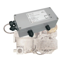
Figure 1: EPE2 ........................................................................................................................... 6
Figure 2: EPE2 Internal overview ................................................................................................ 6
Figure 3: Schematic structure of the device for discharging and refilling “Stand-Alone residue
discharge“ ................................................................................................................................... 7
Figure 4: Schematic structure of the device for discharging and refilling “MultiFlow residue
discharge“ ................................................................................................................................... 9
Figure 5: Connection label in the device cover .......................................................................... 15
Figure 6: Control board REC-1S ............................................................................................... 18
Figure 7: EPE2-Controller Internal overview ............................................................................. 18
Figure 8: Residue discharge function ........................................................................................ 29
9.3 Index of Tables
Table 1: DIP switch S1 settings ................................................................................................. 13
Table 2: Sensor type settings .................................................................................................... 16
Table 3: Display of the operating states with LED’s ................................................................... 31