Sening®
Innovative Tank Truck Systems
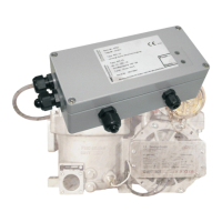
EPE2-
Controller for Meter Draining System
EPE2
Installation Manual
MN F08 003 US / DOK-450E Rev. 1.03 / JS / jp / March 2010 11
2 General installation instructions
In addition to the following points listed, you also have to follow all relevant regulations such as
VDE 0165 during set-up, operation and maintenance. Only when the following recommendations
are followed we can guarantee long and trouble-free operation.
2.1 Preventive measures
2.1.1 For preventing accidents (caused by ignition of gases)
Explosive protection ordinances are to be followed!
The EPE2-Controller are NOT
suitable for use in explosive areas. However
installation of the device in Zone II is permitted.
2.1.2 To meet the requirements stipulated by standards
•
The wiring must be carried out according to the circuit diagrams supplied. The colours of the
wires correspond to DIN 47100. Please follow the colour codes strictly.
•
The electrical installation must be carried out according to EN 60079-14; VDE 0165.
•
No additional components must be added to the EPE2 housing, since this would void the de-
vice approval.
2.1.3 To ensure trouble-free operation
•
Disconnect the power supply during welding on the vehicle.
•
Always mount the cable entries facing to the side or downwards, to avoid water from pene-
trating the housing.
•
Unused PG screw joints should be sealed on the device using waterproof sealing plugs.
•
Protect the terminal- and electronic housings as well as the plugs against direct water spray
(e.g. from the tyres).
•
Install all cables so that they cannot get damaged or kinked.
•
Fit all wires with end sleeves.
•
All electric connections are made using screw clamping technology. The are to be fed into
the housing through the PG-screw joints provided according to their respective cross section.