EPE2-Controller for Meter Draining System
EPE2
Installation Manual
Sening®
Innovative Tank Truck Systems
16 Rev. 1.03 / JS / jp / March 2010 MN F08 003 US / DOK-450E
3.3 Switching outputs for “MultiFlow residue discharge“ operation
During operation of „MultiFlow residue discharge“ none of the EPE2 outputs are switched. The
switching information is transferred via the CAN Bus to the MultiFlow, which then takes over the
control.
When setting the “MultiFlow residue discharge “ the DIP switch S1-
power supply board SVC-2S always has to be set into the “ON
other optional devices can be powered by the flow computer 24V (out) connec-
tion.
3.4 Setting the sensor type
The EPE2-Controller supports 3 types of sensors. The selected switch or sensor is connected to
the J3 input on the REC-1S control board.
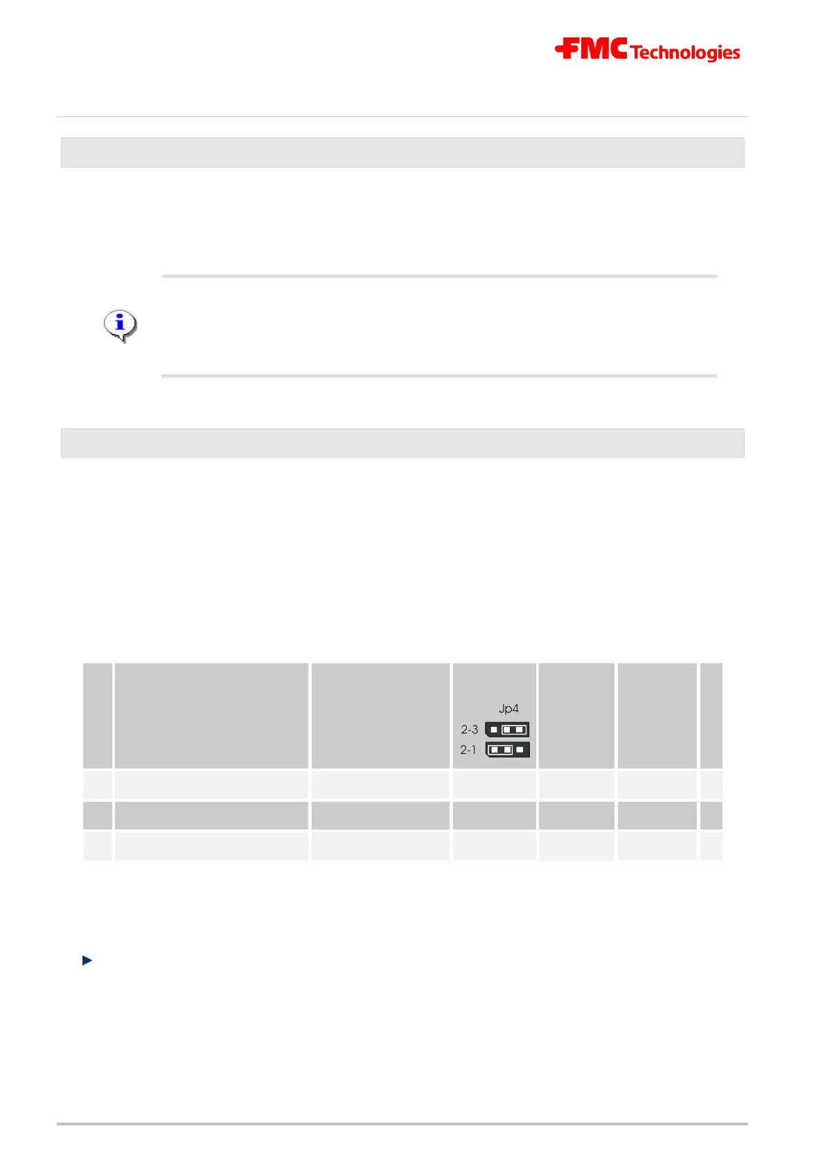
The setting has to be made before commissioning via the jumpers Jp4 and Jp5 on the
REC-1S printed circuit board, listed in the following table.
The 3 sensor types have to be supplied with different voltages. This adjustment is made with the
two jumpers as displayed in the table:
Sensor type
Short circuit
interruption detec-
tion
Jumper
Jp4
Jumper
Jp5
Parame-
ter 2
(via PC or
Laptop)
**
*
1
Sensor with Namur output YES
2-3
inserted
1
◄
2
optoelectronic sensors (NS2) YES
1-2
removed
2
3
mechanical switch NO
1-2
inserted
3
*: Factory or reset settings.
Table 2: Sensor type settings
The proximity switches are Namur set in the factory.