Sening®
Innovative Tank Truck Systems
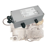
EPE2-
Controller for Meter Draining System
EPE2
Installation Manual
MN F08 003 US / DOK-450E Rev. 1.03 / JS / jp / March 2010 17
3.4.1 Setting the sensor switching logic
REC-1S printed circuit board DIP switch S1-3: ON / OFF
•
The switching logic of the connected sensor is defined with this DIP switch (see Figure 6 /
page 18). It can be set whether the switch is an NO contact (in active state switch is closed)
or NC contact (in active state switch is open). The DIP switch is factory set to ON = “0“ ac-
tive.
If an inverted function of the switching signal is required, then the DIP switch S1-3 has to be
placed in the opposite position.
3.5 Further tips for commissioning
•
For the commissioning of the residue discharge it may be helpful, if the switching output is
continually switched, independent of the input signals.
•
For this the DIP switch S1-2 on the power supply printed circuit board SVC-2S is to be set to
the “ON“ position. The supply voltage (24 volts) is thus always through-connected to the flow
computer connection.
•
If the “Stand-Alone residue discharge “ is to be activated, then the DIP switch S1-2 (SVC-
2S) has to be placed in the “OFF“ position. Now the supply voltage for the flow computer
connection is switched according to the input state.
•
If a PC or Laptop is available, then the relay can also be switched via the service function.
(see also chapter in DOK-512E).