38
Installation and Operation Manual
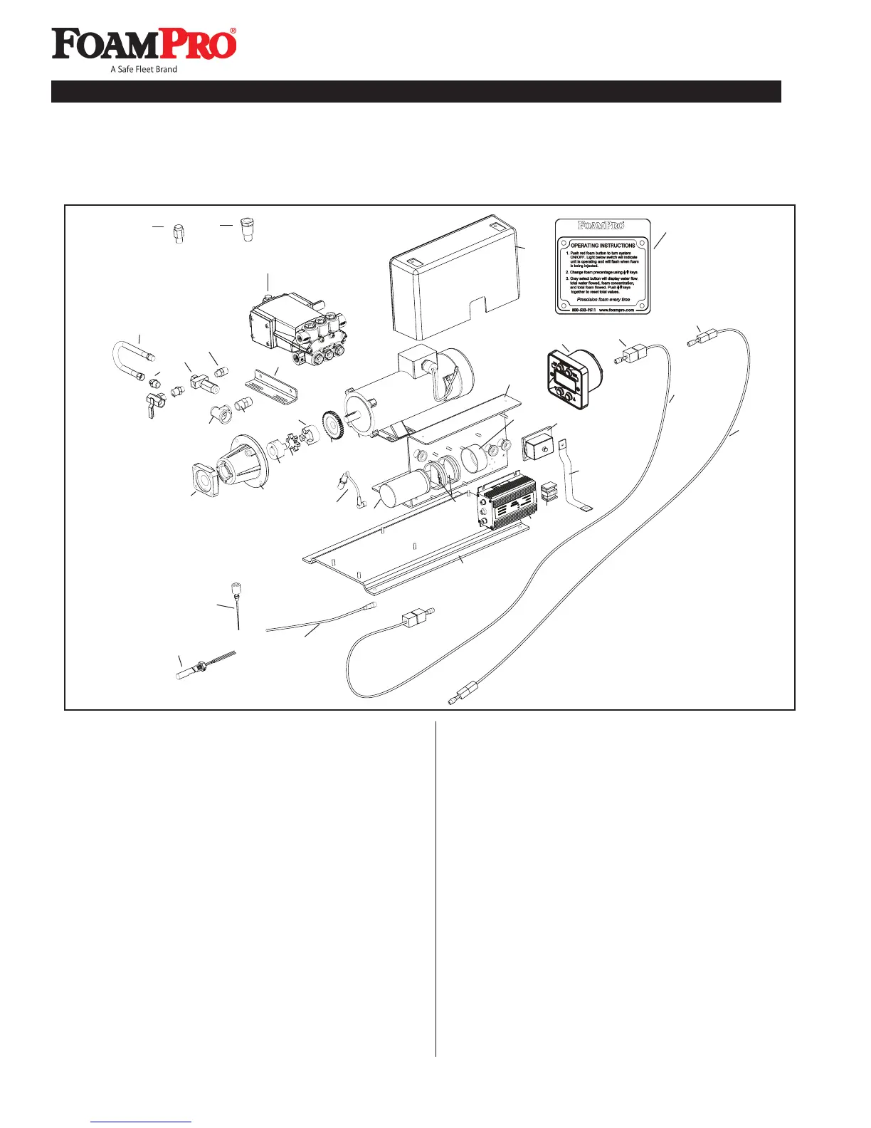
Ref. Part No. Description Qty.
1 2413B-P-01 Foam Pump Assy-2024 1
2 3300-0092 Relief Valve 1
3 3304-0025 Cal/Inject Valve 1
4 2404-0271 Reducer 2
5 2404-0272 Reducer 1
6 2900-0049 Bypass Hose 1
7 2401-0033 Tee 1
8 2402-0034 Nipple 1
9 1520-0096 Pump Base 1
10 2404-0358 Pump Adaptor 1
11 0704-8600A1 Flange Adaptor 1
12 2739-1005 Coupler, 1” 1
13 2729-1001 Rubber Disc 1
14 2739-1003 Coupler, 7/8” 1
15 3900-0056 Timing Gear 1
16 2570-0028 Motor, 1-1/2 HP, 24 VDC 1
17 2530-0092 Speed Sensor 1
18 2530-0087 Capacitor 1
19 2910-0016 Clamp 2
20 1450-0014 Plastic Cap 1
21 1510-0086 Mounting Bracket 1
Ref. Part No. Description Qty.
22 2527-0069 Driver Box 1
23 2530-0097 Terminal Block 1
24 2520-0107 Ground Strap 1
25 2527-0031 Diode Block 1
26 1510-0112 Base 1
27 2840-0071 Cover 1
28 2527-0139 Digital Display Control 1
29 2520-0048 Control Cable (6 ft.[2m]) 1
2520-0049 Control Cable (12 ft. [3 m]) STD 1
2520-0050 Control Cable ( 20 ft. [5m]) 1
30 3430-0351 RFI Kit for Controller 1
31 2520-0045 Flowmeter Cable ( 6 ft. [2 m]) 1
2520-0046 Flowmeter Cable (12 ft. [3m]) STD 1
2520-0047 Flowmeter Cable (20 ft. [5m])
32 3430-0353 RFI Kit for Flowmeter 1
33 2520-0042 Tank Sensor Cable 1
34 2510-0032 Tank Level Sensor (Side) 1
35 2520-0028 Tank Level Sensor (Vertical) 1
36 3320-0055 Injection Check Valve 1
37 2404-0182 Injector Fitting (Optional) 1
38 6032-0012 Instruction Placard 1
Parts Identification for System 2024
38
37
36
3
12
10
35
34
33
14
13
7
11
17
18
19
20
24
25
23
22
26
21
8
9
2
4
5
4
6
1
16
15
32
30
29
31
28
27