AUTO REFILL CONTROL (ARC) OPTION
QUESTIONS ? Help Hotline: 1-800-893-6723
W.24
File: T4\NEW O&M 2007\W24 WIZ NEW PR328 ARC START.tcw
04/08/08 MT
ARC QUICK START GUIDE
(See below for complete ARC information)
Connect transfer device (solenoid valve, transfer pump, secondary relay) to 2-pin connector
plug located below relay module on Wizard motherboard slot J7. If more than one channel
has ARC option: RELAY 1 = Ch. 1, RELAY 2 = Ch. 2, etc.
Set ARC Mode to LEVEL or BATCH and set refill values. (SETUP MENU "10 AUTO REFILL").
LEVEL refills to preset level, BATCH adds preset amount.
(located on Wizard door): Press in to STOP refill. Rotate
button clockwise to release and reset.
Insure tank has some form of secondary overfill protection such as high level float switch
or sealed day tank with vent line leading back into bulk tank.
1.
INJURY OR DEATH CAN RESULT FROM CHEMICAL SPILLS OR
IMPROPER OPERATION !
CAREFULLY DETERMINE & SET REFILL START AND STOP VALUES.
VISUALLY OBSERVE ONE COMPLETE REFILL CYCLE BEFORE
UNMANNED OPERATION. READ COMPLETE OPERATION MANUAL.
WARNING
2.
3.
4.
The Wizard can be purchased with up to four (4) Auto Refill Control options (one per channel).
The ARC option consists of an Emergency Stop Button located on the front of the enclosure,
pre-installed software and a control relay.
The standard ARC relay provided is a solid state, normally open relay. This relay requires a minimum
loop current of 20mA with a maximum motor load of 1.5 amps. The relay typically activates a transfer
pump, solenoid valve or other device provided by others which allows the transfer of chemical from
bulk storage to day tank, or controls the addition of water to the day tank for mixing.
If the relay signal is to be taken directly into a PLC, a dry contact relay is available. Please contact
factory for dry contact relay. Solid state relay modules are BLACK, dry contact modules are RED.
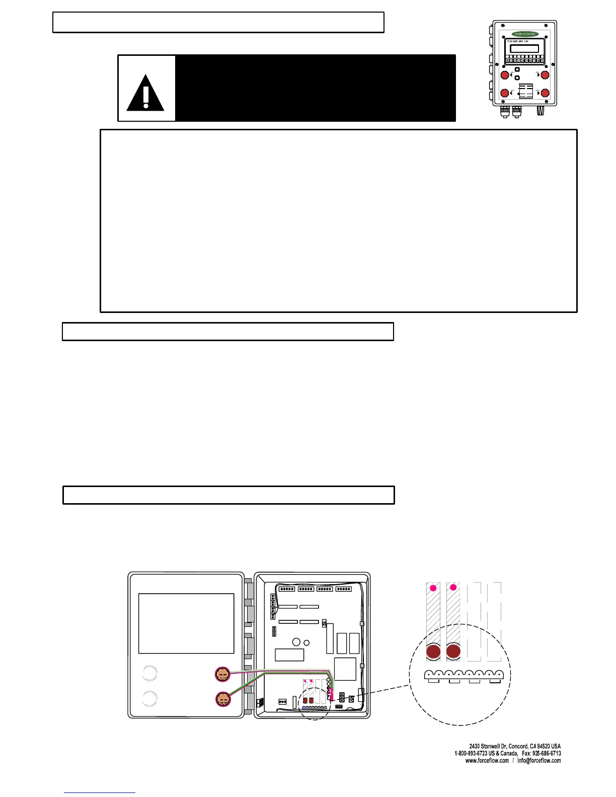
Connect the two wires from your transfer device to the 2-pin plug connector located in socket J7
as marked on the motherboard. This socket is located along the lower edge of the motherboard
directly below the relay module(s).
SETPOINT #4 (HI LEVEL ALARM)
SETPOINT #3 ( TRANSFER PUM P OFF)
SETPOINT #2 (T RANSFER PUM P ON)
SETPOINT #1 (LOW ALARM)
LIGHT
ON
LIGHT
OFF
TANK
LOAD
STEP 1:
STEP 2:
DISPLAY
SELECT
TOGGLES THROUGH DISPLAY OPTIONS:
NET REMAINING AMOUNT US ED
AVERAGE FEED RATE DAYS UNTIL
EMPTY DAI LY USAGE
PRESS "TANK LOAD" BUTT ON.
FILL YOUR TANKS NOW!, THEN
PRESS"ENTER".
ALLOWS MANUAL REFILLING OF TANKS,
WHILE MAINTAINING ACCURATE USAGE
DATA (DO NOT FILL TANKS UNTIL "STEP 2 ")
24
13
LOAD CELL/ULTRASONIC CONNECTIONS
#1 #2 #3 #4
DISPLAY ANGLE
ADJUSTMENT (BLUE)
E
P
R
O
M
RAM
CPU
POWER
SUPPLY
POWER IN
#
1
#
2
#
3
#
4
FUSE
P
1
+
2
4
V
D
C
f
o
r
U
l
t
r
a
s
o
n
i
c
s
+
_
R
G
T
R
S
4
8
5
R
S
2
3
2
ARC OPTION #1
#1
#2
#3 #4
ARC OPTION #2
ARC OPTION #3
ARC OPTION #4
ARC OPTION
CHANNEL #1
ARC OPTION
CHANNEL #2
ARC OPTION
CHANNEL #3
ARC OPTION
CHANNEL #4
EXAMPLE OF 2 CHANNELS
ARC OPTION #1
#1
#2
#3
#4
ARC OPTION #2
ARC OPTION #3
ARC OPTION #4
PLUG 1
PLUG 2
PLUG 3
PLUG 4
J7
DESCRIPTION
WIRING
Emergency Stop Button
NOTE: FULL DRAWING ON PAGE W.10
(OPTION MODEL NO. ARC4000)