Forcepoint Next Generation Firewall Hardware Guide | Models 330, 331, 335, 335W
4
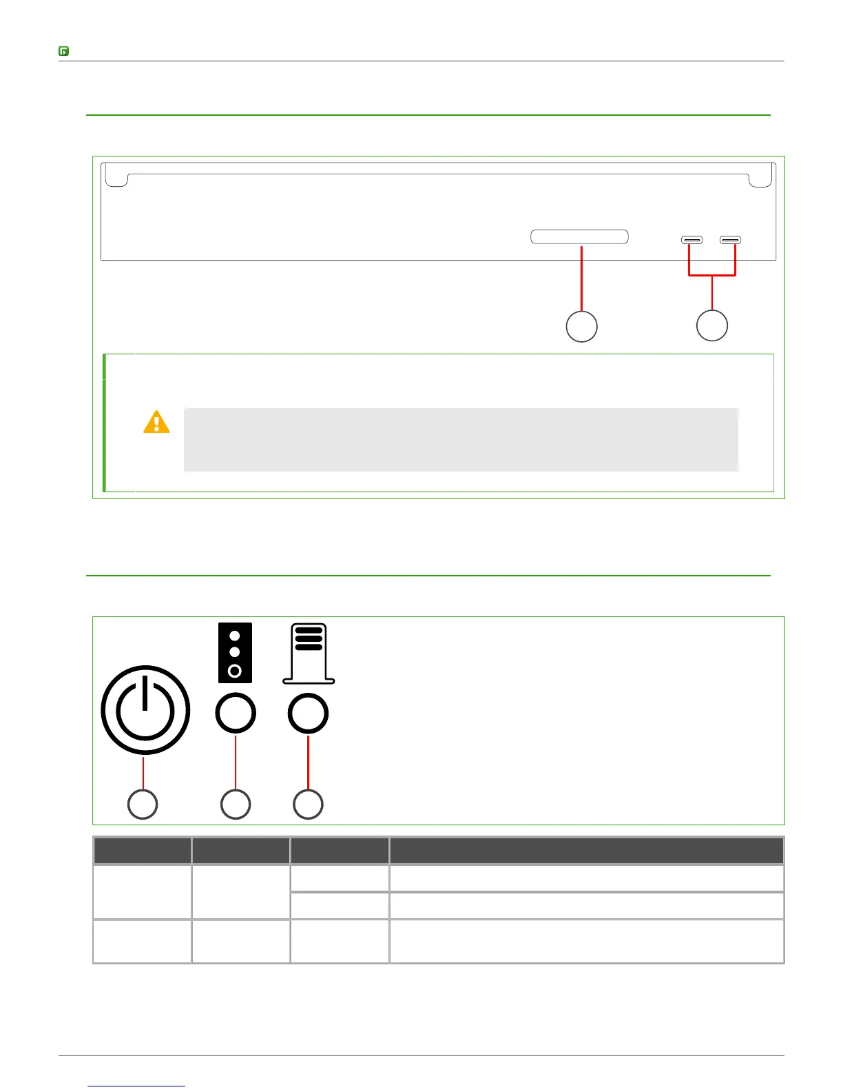
Back panel
The back panel includes the CFast Card and the power connectors.
1
2
1 CFast Card
2 19V DC power connectors A and B from left to right
CAUTION: The power connectors are intended to provide power to the Forcepoint
appliance only. Do not connect other devices to the power connectors. Use only the
power adapter delivered with the Forcepoint appliance to power the appliance.
Indicator lights
Indicator lights show the status of the appliance and the fixed Ethernet ports.
1 2 3
Number Indicator Status Description
Green The appliance is running.1 Power
Red The appliance is in a standby state.
2 Software
status
Flashing
amber
Initial contact between the NGFW Engine and the
Management Server has not yet been established.