25
TABLE OF CONTENTS
DECLARATION OF CONFORMITY ................................ 2
SECTION 1 - Description and specications of the
machine
1.1 Foreword. ...................................................... 26
1.2 Warranty ....................................................... 26
1.2.1 Warranty exclusions ..................................... 26
1.3 Identication of the machine ......................... 27
1.4 Description of the machine and authorized ... 27
1.4.1 Authorized use of the machine ...................... 27
1.4.2 Unauthorized use of the machine .................. 27
1.4.3 Control and driving position .......................... 28
1.5 Protections and safety devices ...................... 28
1.5.1 Noise level ..................................................... 28
1.5.2 Vibrations level ............................................. 28
1.6 Techincal specications ................................ 29
SECTION 2. Safety and prevention
2.1 Safety ............................................................ 30
2.1.1 Words used ................................................... 30
2.1.2 General safety regulation .............................. 30
2.2 Safety signals ................................................ 31
2.3 Safety while operating and maintenaing ........ 31
SECTION 3: Transport
3.1 Transport ...................................................... 32
SECTION 4: Use
4.1 Before using the machine ............................. 33
4.1.1 Adjustment of the handlebars ....................... 33
4.1.2 Tyres and wheel thread adjustment .............. 34
4.1.3 Installation gearbox rod and clutch ............... 34
4.1.4 Replacement intercangeable equipment ........ 34
4.1.5 Preliminary checks ........................................ 35
4.2 Starting ......................................................... 35
4.2.1 Pull start of the gasoline engine .................... 35
4.2.2 Pull start of the diesel engine ........................ 35
4.2.3 Electric starter on machine with lights .......... 36
4.2.4 Electric starter on machine without lights ..... 36
4.2.5 After starting ................................................. 36
4.2.6 Beams switch ................................................ 36
4.3 Forward movement - shifting ........................ 37
4.3.1 Reverse ......................................................... 37
4.4 During operation ........................................... 37
4.4.1 Use of the machinee on slopes ..................... 37
4.4.2 Parking .......................................................... 38
4.5 Differential locking ........................................ 38
4.6 Power takeoff ................................................ 38
4.7 Stopping of the engine .................................. 38
4.7.1 Engine stop for machines with electric start. 38
4.8 After use ....................................................... 39
SECTION 5: Ordinary maintenance
5.1 General information ...................................... 39
5.2 Engine maintenance ...................................... 39
5.3 Machine maintenance ................................... 39
5.3.1 Adjustment of the clutch control ................... 40
5.3.2 Adjustment of the accelerator control ........... 40
5.4 Extraordinary maintenance ........................... 40
5.5 Setting at rest ................................................ 40
5.6 Machine dismantling ..................................... 40
5.7 Spare parts ................................................... 40
5.8 Troubleshooting ............................................ 41
DESCRIPTION OF FIGURES
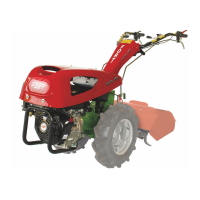
Figure 1 - Overview of the tiller. - 1) Nameplate. - 2)
Serial number. - 3) Steering handles. - 4) Engine. - 5)
Drive wheels. - 6) Bonnet. - 7) Milling unit. - 8) Lever
throttle. - 9) Reverser lever. Lets reverse the direction
of rotation and the rotation of the PTO. - 10) Device en-
gine off. Turn off the engine from the command post of
the machine. - 11) Lever for locking and lateral regula-
tion handlebars. - 12) Rod gearchange. - 13) Auction
engaging/disengaging the PTO. - 14) Handlebar height
adjustment lever. - 15) Differential lock lever. - 16)
Clutch lever. Pressed, after having disengaged the lo-
cking device 17 permits the engaging and disengaging
the clutch. - 17) Device locking / unlocking clutch lever
(only when pressed allows you to pull the clutch lever
and activate the functions of the machine to release the
clutch lever (ref. 16) blocks the same upright and clutch
lever).
Figure 2 - Dimensions.
Figure 3 - Position hand lever starter motors with ma-
nual set in motion.
Figure 4 - Adjusting the clutch. - 1) Lock the clutch
cable. - 2) Register clutch cable. - 3) Screw the end of
the race the clutch lever. - 4) External clutch lever.
Figure 5 - Reversing handlebars. - 1) Spring pin lo-
cking rods. - 2) Auction engaging / disengaging the
PTO. - 3) Rod gearchange. - 4) Position rod ends. - 5)
Locking lever and handlebars side adjustment. - 6) Point
coupling rod lever. - 7) Fixing screws interchangeable
equipment. - 8) Connections for trailers. - 9) Through
holes of support rods. - 10) PTO shaft. - 11) Adhesive
signaling the direction of rotation for the reversal of the
handlebars.
Figure 6 - Attachment points for the lifting machine.
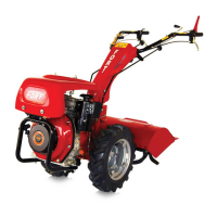
Figure 7 -
A) Machine with milling unit. B) Machine with
handlebars reversed and cutterbar. The levers gearbox and
PTO are different and should be mounted as shown in this
gure.
Figure 8 - Replacemento gearbox oil. - 1) oil level plug.
- 2) Vent plug and ll; removing the ll plug from its
mounting hole to the change, you can top up or replace
the gearbox oil. - 3) Gearbox oil drain plug (is positioned
on the opposite side to the one represented on gure). - 4)
Machine serial number.
Figure 9 - Track wheeled adjustable
Figure 10 - Electrical panel for machines equipped with
electric start engine and working light front.
Figure 11 - Safety signs and their location on the
machine (for their description see 2 Safety).
ENGLISH