33
safe area where it is possible to move quickly in case
the load falls.
Before loading, make sure that the body of the means
of transport is large enough to transport the machine
DANGER
The area where you intend to load the machine shall
be a rm level surface to avoid load shift, if any.
- The means of transport shall have the engine shut
off, the gear and the parking brake on.
- The loading and the unloading shall be always
performed with an empty machine (with no load).
- Load the machine by walking at a low travel
speed (1st speed or reverse speed and engine at
the minimum rpm), by being careful to correctly
enter the ramps and to walk on the ramps safely.
Once the machine is loaded onto the means of
transport, make sure it is well locked in its posi-
tion.
Tighten securely the machine onto the platform with
ropes or well-tightened chains to prevent it from
moving,
After transporting it and before untying the machine,
check that the shape and the position of the machine
are not a hazard.
Then remove all ropes and chains and unload it with
the same means and procedures used for loading.
SECTION 4
Use
4.1 BEFORE USING THE MACHINE
WARNING
Before setting the machine at work, the operator
shall read and understand all parts of this manual
(as well as the engine manual) and in particular
what is written in «Section 2» (Safety).
Moreover, before starting the machine, check that
the machine is in good working conditions and that
all parts subject to wear are fully efcient.
The machine is partially disassembled before packing
it. Therefore, it is necessary to assemble it according
to the following instructions:
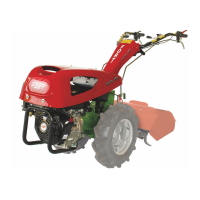
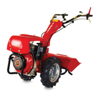
4.1.1 ADJUSTMENT OF THE HANDLEBARS
If the machine is packed, the handlebars are on the
engine casing. Otherwise they are positioned as
shown in Fig. 1.
Before using the machine, adjust the height of the
handlebars and position them according to the type
of attachment.
Adjustment of height:
Push down the lever (14 Fig. 1) and keep it in un-
locked position, adjust the handlebars to the desired
height, then release the lever (14 Fig. 1) and insert the
handlebars clip pin in the nearest hole to the chosen
position (4 options).
Horizontal adjustment:
The lateral movement of the handlebars is possible
both with version machine rotary hoe (conguration
A Fig. 7) in that version cutter (conguration B Fig. 7).
Do as follows: deeply pull the lever (11 Fig. 1); move
the handlebars to the right or left until the clip pin
coincides with the prearranged hole.
Then release the lever (11 Fig. 1), (a right position, a
left position, and a central one are available).
180° Handlebars rotation
In order to assemble front interchangeable equipment
(mowing bar, snow-plough,…), it is necessary to
put the handlebars on the engine bonnet, operating
as follows:
1) Remove the elastic pins (1 Fig. 5) securing the
ENGLISH