21
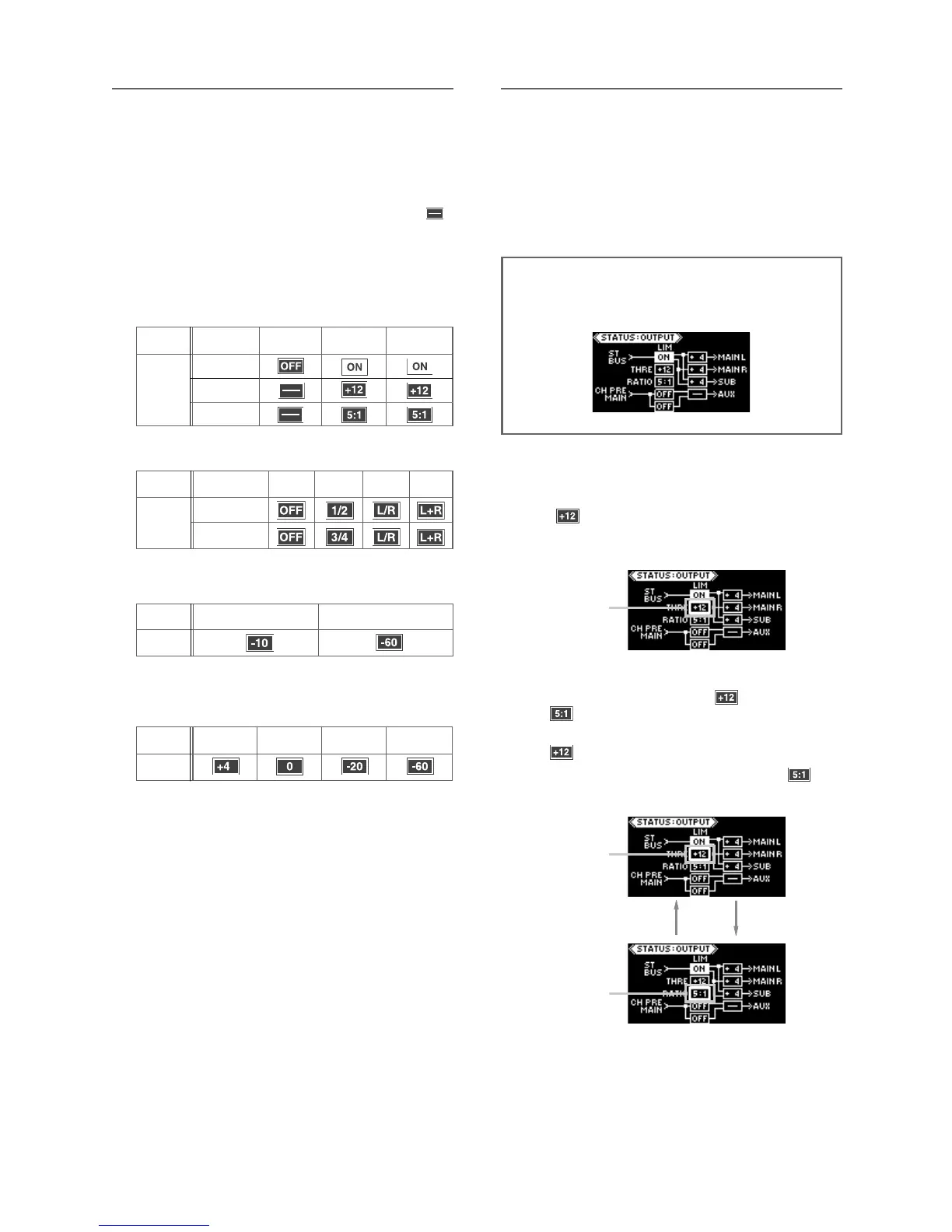
When the [LIMITER] switch is set to “OFF”, the pa-
rameter boxes for the threshold and ratio show “
”.
When the [LIMITER] switch is set to “ON” or “LINK”,
the parameter boxes for the threshold and ratio
show the current parameter values.
You can edit the parameter values by following the
procedure described in the next page.
OFF
ON
LINK
THRE
RATIO
-10
-60
+4
The following icons are shown according to the switch set-
ting.
0
-10 -60
• [LIMITER] switch status
• AUX OUT switch status
• AUX OUT level switch
• SUB OUT level switch
• MAIN OUT (L, R) level switches
Icon
Icon
Switch
setting
Icon
Switch
setting
Switch
setting
OFF
1/2 , 3/4 L/R L+R
Switch
setting
Icon
Status information details
Upper (AUX 1)
Lower (AUX 2)
Limiter parameter setting
(1) While the output status display is shown,
press the [EDIT] key long enough.
“ ”, the current THRE value, starts flashing
quickly.
You can now edit the threshold level.
<Note>: In the following description, it is assumed
that the [LIMITER] switch on the front panel is set to
“ON” and the input status display looks as below.
(2) By pressing the [EDIT] key, you can alter
-
nately flash the THRE (“ ”) and RATIO (“
”) values.
To edit the threshold level, flash the THRE value (“
”).
To edit the ratio, flash the RATIO value (“ ”).
Flashing
Flashing
Flashing
By setting the [LIMITER] switch to “ON” (or “LINK”),
the limiter function is enabled and you can apply
the limiter to the stereo L/R buss.
The threshold level and ratio (compression ratio) of
the limiter are set to “+12” and “5.1” respectively
by default.