7
(1) Connect a microphone or line level source to
each of the [INPUT] connectors (1 through 4).
(2) When you connect a microphone, set the
input select switch to “MIC”. When you con
-
nect a line level source, set the input select
switch to “LINE”.
(3) When you connect a microphone, set the mi
-
crophone power supply switch appropriately.
When you connect a condenser microphone that
requires +48 V phantom power, set the switch to
“P48”. When you connect a condenser micro
-
phone that requires T-12 power (A-B 12 V) such as
Sennheiser 416T, set the switch to “P48”. When
you connect a dynamic microphone, set the switch
to “DM”.
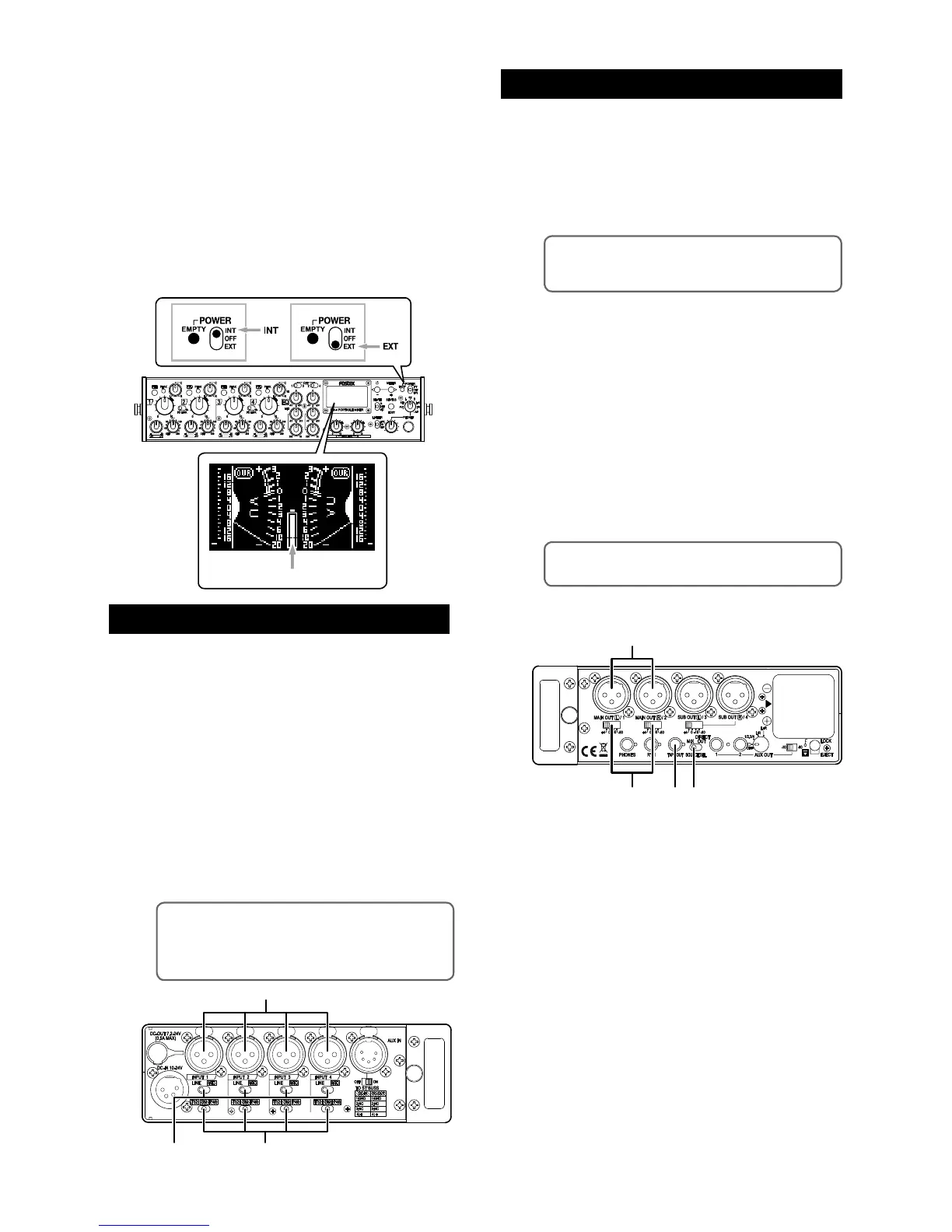
• To send the stereo output signals to an external
audio device
You can send the stereo mixed signals to an external audio
device from the [MAIN OUT] (L/1, R/2) connectors.
(1) Set the [SOURCE SEL] switch to “MIX”.
<Memo>:
The [SUB OUT] (L/3, R/4) connectors
also send the same signals as the [MAIN OUT] (L/1,
R/2) connectors.
(2) Connect an external audio device such as a
recorder to the [MAIN OUT] (L/1, R/2) con-
nectors.
(3) Set the output level switch appropriately de
-
pending on the device connected.
You can set the nominal output level to +4
dBu, 0 dBu, -10 dBu or -60 dBu.
(4) To connect a -10 dBV unbalanced line level
device, use the [TAPE OUT] jack (stereo mini
jack). The nominal output level of this jack is
fixed to -10 dBV.
<Memo>:
The stereo buss signal is output from
the [TAPE OUT] jack.
You can turn on the unit by setting the [POWER]
switch on the front panel to “INT” (upper position) or
“EXT” (lower position). When you operate the unit on
internal battery power, set the switch to “INT”.
When you operate the unit on external power, set it
to “EXT”. When you turn on the unit for the first time,
the display shows the stereo VU meters as shown
below. When you operate the unit on (internal
on external) battery power, confirm that the battery
power is sufficient by checking the battery indicator
on the meter display.
You can check the power voltage of the battery pow
-
er source from the system status display (see page
23).
<Memo>: If you do not need T12 (A-B 12 V)
power supply capability, you can disable this ca
-
pability from the input status display. By default, it
is enabled. See page 19 for details.
• To output each input signal directly
You can send “post-fader” input signals of the INPUT 1
through 4 from the [MAIN OUT] (L/1, R/2) and [SUB OUT]
(L/3, R/4) connectors respectively.
(1) Set the [SOURCE SEL] switch to “DIRECT
OUT”.
(2) Connect the external device(s) to the [MAIN
OUT] and/or [SUB OUT] connectors.
(3) Set the output level switch appropriately to
match the external device.
You can set the nominal output level to +4
dBu, 0 dBu, -10 dBu or -60 dBu.
Preparation of input channels
Preparation of output channels