14
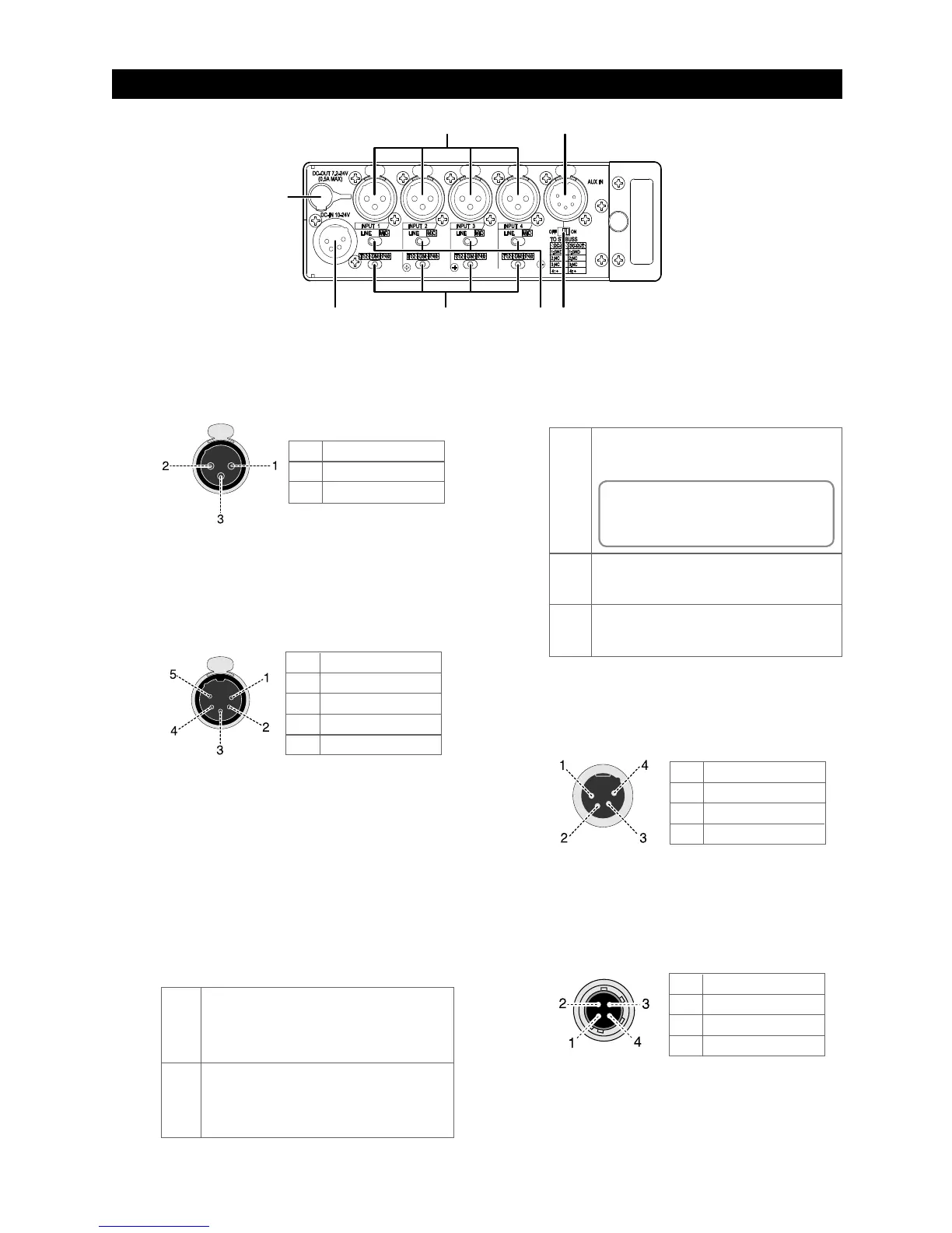
1. [INPUT] connector (1 through 4)
Each connector is used to connect an external au-
dio
device or microphone.
Connector: XLR-3-31 type
3. [TO ST BUSS] switch (ON / OFF)
This switch selects whether or not the input signal
from the [AUX IN] jack is sent to the stereo buss.
To send the [AUX IN] signal to the stereo buss, set
the switch to ON. When the switch is set to OFF,
the [AUX IN] signal is not sent to the stereo buss.
Regardless of the switch setting, you can monitor
the
[AUX IN] signal via headphones.
2. [AUX IN] connector
Used to connect a mixer or audio device.
Not only you can monitor the input signal of this
connector, you can send the signal to the stereo
buss to mix with the main input signals (selectable
with the [TO ST BUSS] switch).
Connector: XLR-5-51 type
7. [DC OUT 7.2-24V] connector
This connector outputs power at DC 7.2 to 24 V / 0.5 A
for a wireless receiver, etc.
It outputs power when the unit is powered on.
Connector: Hirose 4-pin HR10A-7R-4S
6. [DC IN 10-24V] connector
Used to connect the supplied AC adaptor (or an
external battery).
Connector: XLR-4-32 type (male)
1
2
3
4
GND
NC
NC
DC 10 V to 24 V
1
2
3
4
GND
Lch HOT
Lch COLD
Rch HOT
5 Rch COLD
1
2
3
GND
HOT
COLD
1
2
3
4
GND
NC
NC
DC 7.2 V to 24 V
4. Input select switches (LINE / MIC)
Each switch should be set appropriately according
to
the input signal source of the corresponding [IN-
PUT] connector.
DM
P48
No microphone power is supplied. When you
connect a dynamic microphone, set the switch
to DM.
48-volt phantom power supply mode.
A 48 V power is supplied to the hot and cold
terminals of the [INPUT] connector.
T12
T12 or AB power supply mode. A 12 V power is
supplied to the hot terminal of the [INPUT] con-
nector.
5. Microphone power supply switches
(T12 / DM /P48)
Each switch sets whether or not supplying the
mi-
crophone power.
MIC
You should set the switch to MIC when a micro-
phone is connected to the [INPUT] connector.
You can supply the microphone power when
connecting a condenser microphone (see “Mi-
crophone power supply switch” below).
LINE
You should set the switch to LINE when a line-
level source is connected to the [INPUT] connec-
tor. When it is set to LINE, the microphone power
supply is automatically turned off regardless of
its setting.