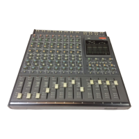
13
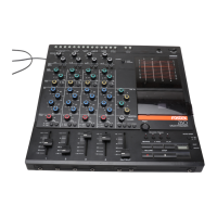
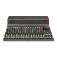
16. [MASTER] faders (L and R)
These faders control stereo left and right buss
output levels. The scale position in orange shows
the reference position. A pop-up type knob is used
for each fader. It pops up when you push it once.
Pushing it again makes it locked on the same level
as the panel.
17. [MIC] (Slate microphone)
A slate microphone is built in. While holding down
the [SLATE] switch to the “MIC” position, the
slate microphone is active and the signal from the
microphone is sent to the stereo buss.
18. EQ controls
These cotrols adjust EQ setting.
The FM-4 provides two EQ channels featuring the
HI and sweepable MID bands.
HI
MID
Shelving
Sweepable
Band Type
10 kHz
200 Hz to 8 kHz
Frequency
-12 dB to +12 dB
-12 dB to +12 dB
Gain range
The three controls on the left side adjust the EQ for
the input channel selected by the EQ 1-3 switch,
while the three controls on the right side adjust the
EQ for the input channel selected by the EQ 2-4
switch.
From the top row, these are the HI gain, MID gain
and MID frequency controls.
A pop-up type knob is used for each EQ control. It
pops up when you push it once. Pushing it again
makes it locked on the same level as the panel.
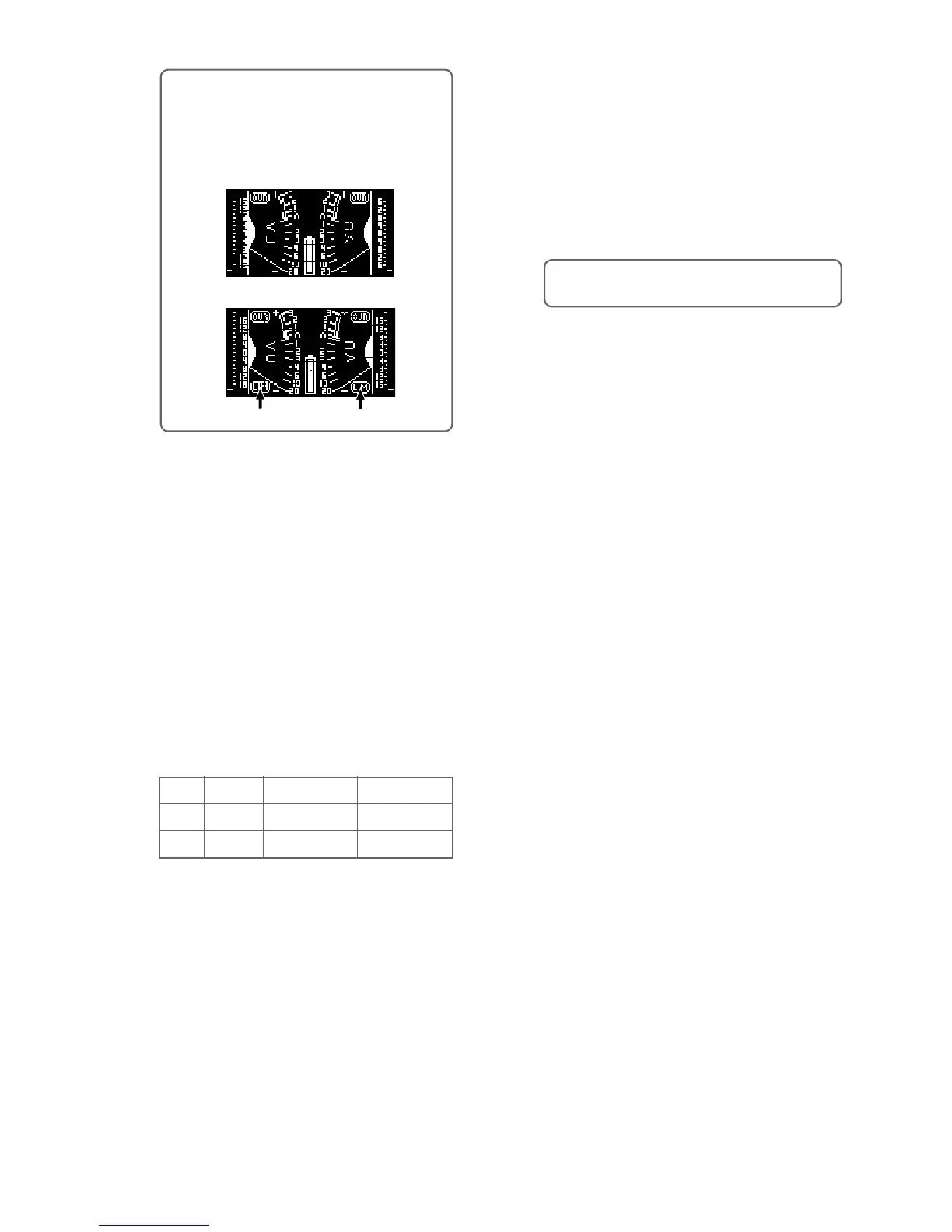
<Memo>: When you select the [LIMITER]
switch to ON or LINK, the meter display shows
“LIM” (pointed by arrows below). When the
limiter is working, “LIM” flashes. The following
shows display examples of the stereo meter
display.
When the switch is set to OFF
When the switch is set to ON or LINK
“LIM” icon
“LIM” icon
19. HPF controls (1 through 4)
Each control sets the high pass filter function.
At the left-most position (OFF position), the HPF
circuit is bypassed. Rotating the control knob
clockwise switches on the HPF (with a click). De
-
pending on the position, you can set the HPF cut-
off frequency between 40 Hz and 200 Hz (at -12
dB/oct.).
A pop-up type knob is used for each HPF control.
It pops up when you push it once. Pushing it again
makes it locked on the same level as the panel.
<Memo>: The HPF cuts the unnecessary low fre-
quency range, such as wind blowing.
20. Channel faders (1 through 4)
Each fader controls the signal level sent to the ste-
reo buss.
The scale position in orange shows the reference
position.
21. Input trim controls (1 through 4)
Each control adjusts the input gain of the cor-
responding input channel. When the input select
switch is set to MIC, you can adjust the gain be
-
tween -70 dBu and -30 dBu.
When the input select switch is set to LINE, you
can adjust the gain between -20 dBu and +4 dBu.
It is recommended to adjust the control so that the
PEAK indicator does not light in red at the maxi
-
mum input level.
A pop-up type knob is used for each control. It
pops up when you push it once. Pushing it again
makes it locked on the same level as the panel.