2
16
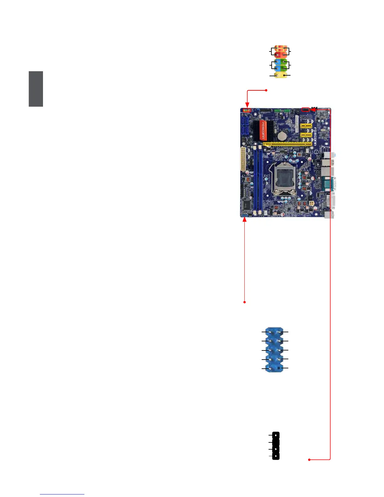
Front Panel Connector : FP1
This motherboard includes one connector for connecting
the front panel switch and LED Indicators.
Hard Disk LED Connector (HDD-LED)
Connect to the chassis front panel IDE indicator LED.
Itindicatestheactivestatusoftheharddisks.This2-
pin connector is directional with +/- sign.
Reset Switch (RESET-SW)
Attach the connector to the Reset switch on the front
panel of the case; the system will restart when the
switch is pressed.
Power LED Connector (PWR-LED)
Connect to the power LED indicator on the front panel
of the chassis. The Power LED indicates the system’s
status. When the system is in operation (S0 status),
the LED is on. When the system gets into sleep mode
(S1),theLEDisblinking;WhenthesystemisinS3/
S4sleepstateorpoweroffmode(S5),theLEDisoff.
This2-pinconnectorisdirectionalwith+/-sign.
Power Switch Connector (PWR-SW)
Connect to the power button on the front panel of
the chassis. Push this switch allows the system to be
turned on and off rather than using the power supply
button.
COM Connector : COM2
Thismotherboard supports one serial RS232 COM port
for legacy compatibility. User must purchase another
RS232cablewitha9-pinD-subconnectoratoneendto
connectwiththeexternalRS232deviceandanotherend
with 10-pin female connector to connect with COM1 con-
nector in the motherboard.
S/PDIF OUT Connector : SPDIF_OUT
The connector is used for S/PDIF output.
HDD-LED
RESET-SW
NC
+
-
PWR-SW
+
-
PWR-LED
EMPTY
1
2
10
9
FP1
RLSD
SOUT
RI
GND
RTS
DSR
DTR
CTS
EMPTY
SIN
1
2
109
COM2
+5V
EMPTY
SPDIF_OUT
GND
1
2
3
4
SPDIF_OUT