Installation | 25
FRAKO | Operating Manual | Power Quality Controller – PQC
5.2.8 Output relays (control outputs)
Depending on instrument type, the PQC is equipped with 6 or 12 output relays (con-
trol outputs). Relays or contactors are usually connected to these to switch the capac-
itor stages in and out.
The output relays Q1–Q12 (Q1–Q6 in the case of PQC versions with 6 output relays)
receive their control voltage from a common feed P. The load ratings of the output
relays and the common feed line P can be found in the connection diagrams or the
technical data (see Section 3 “Technical data”).
If not all of the available output relays are to be used, it is recommended to connect
the output cables starting with output 1 and leaving no gaps.
5.2.9 Alarm function
The PQC has a volt-free contact to transmit alarms externally, alarm terminals a and b
being provided for this external connection as shown in the diagrams in Section 5.2.10
“Connection diagrams for all PQC types”. Attention must be paid to the load rating of
the contact (see Section 3 “Technical data”).
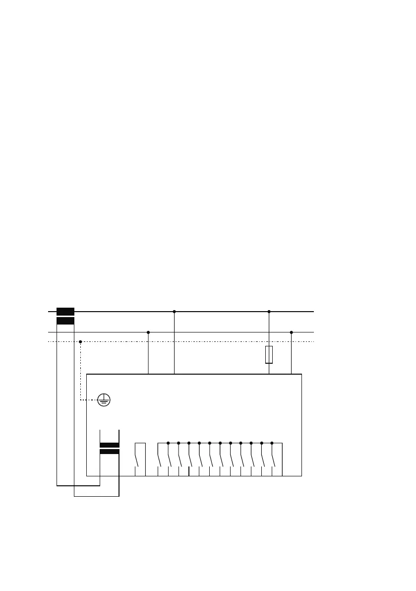
5.2.10 Connection diagrams for all PQC types
5.2.10.1 Connection diagram: Type PQC 1202401-xx
max.6A
N
ba
L/NL L/NL
2A T
AUX
S2S1
L
max.10A
Alarm
Q1
Q11
Q10
Q9
Q8
Q7
Q6
Q5
Q4
Q3
Q2
Q12
P
Ausgangsrelais
output relays
250VAC~ 3A cos
φ =1
Alarmrelais
alarm relays
250VAC~ 3A cos φ =1
Versorgungsspannung
supply voltage
100V-15% – 240 V+10% AC~5 VA
Messspannung
voltage measurement
100V– 690 VAC~ VDE