Description of the menu | 41
FRAKO | Operating Manual | Power Quality Controller – PQC
6.2.3 Service
Main menu > Display > Service
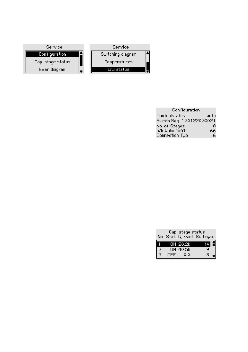
6.2.3.1 Conguration
Main menu > Display > Service > Configuration
Control status Automatic or manual control
mode
Switching sequence Display of the capacitor stages
detected. The relative values
(switching sequence) can be
distributed over the available stages as desired. The largest
permitted relative value is 16, the smallest 0.
Available stages Number of capacitor stages detected
c/k setting [mA] The response current is determined from the smallest capaci-
tor stage detected
Connection type Type of connection for L1, L2 and L3 current transformers.
See Table in Section 5.3.4 “Manual connection and stage
identification”
6.2.3.2 Stage status
Main menu > Display > Service > Stage status
No. No. of the stage [1–12]
Stat. (status) ON / OFF / [x seconds]
ON: Switches stage in manually
OFF: Switches stage out manu-
ally [x seconds]: Time remaining
until the capacitor stage can be switched in again (discharge
time)
Q[var] This is the stage corrective power in var (3-phase stage
corrective power).
Switching cycles Number of stage switching cycles