42 | Description of the menu
Power Quality Controller – PQC | Operating Manual | FRAKO
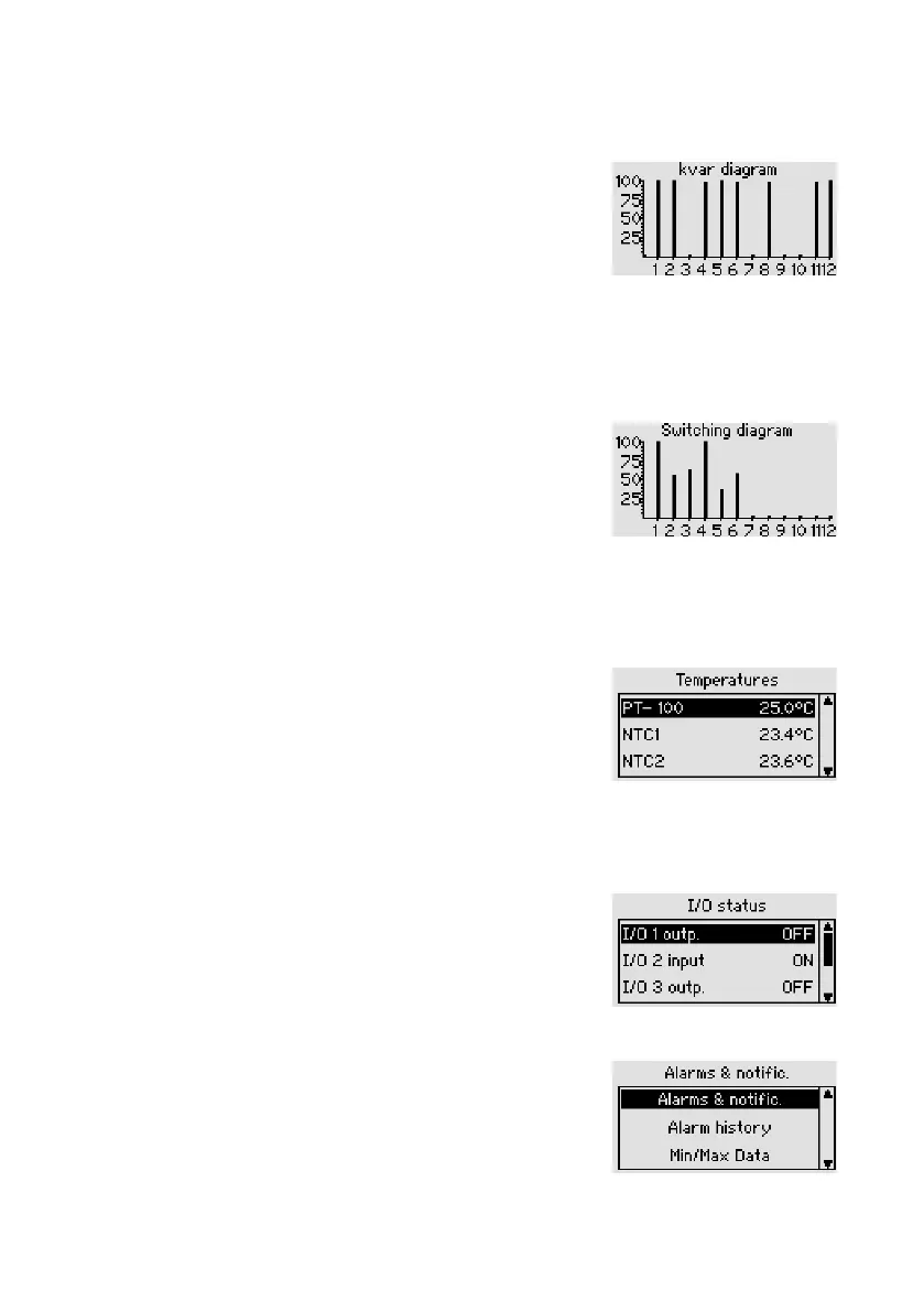
6.2.3.3 Kvar diagram
Main menu > Display > Service > Kvar diagram
The capacitor stages rating diagram shows the
momentary corrective power of the capacitor stages as
a percentage. After the instrument has been started up,
this graphic shows every detected stage as 100%. With
time, however, capacitor wear causes this corrective
power to fall.
6.2.3.4 Switching diagram
Main menu > Display > Service > Switching diagram
This diagram shows the switching cycle counters for all
the stages as a column chart. 100% on the y-axis rep-
resents the set limit for the number of switching cycles
counted.
6.2.3.5 Temperatures (optional temperature I/O extension)
Main menu > Display > Service > Temperatures
Displays the temperature from the activated
PT100 / 1000, NTC1 and NTC2 probes.
6.2.3.6 Temperatures (optional temperature I/O extension)
Main menu > Display > Service > I/O Status
Shows the available inputs and outputs of the tempera-
ture I/O extension and indicates the status of each.
6.2.4 Alarms & notications
Main menu > Display > Alarms & notific.
Status of the momentary alarms Display of Alarms and
Min/Max histories.