28 | Installation
Power Quality Controller – PQC | Operating Manual | FRAKO
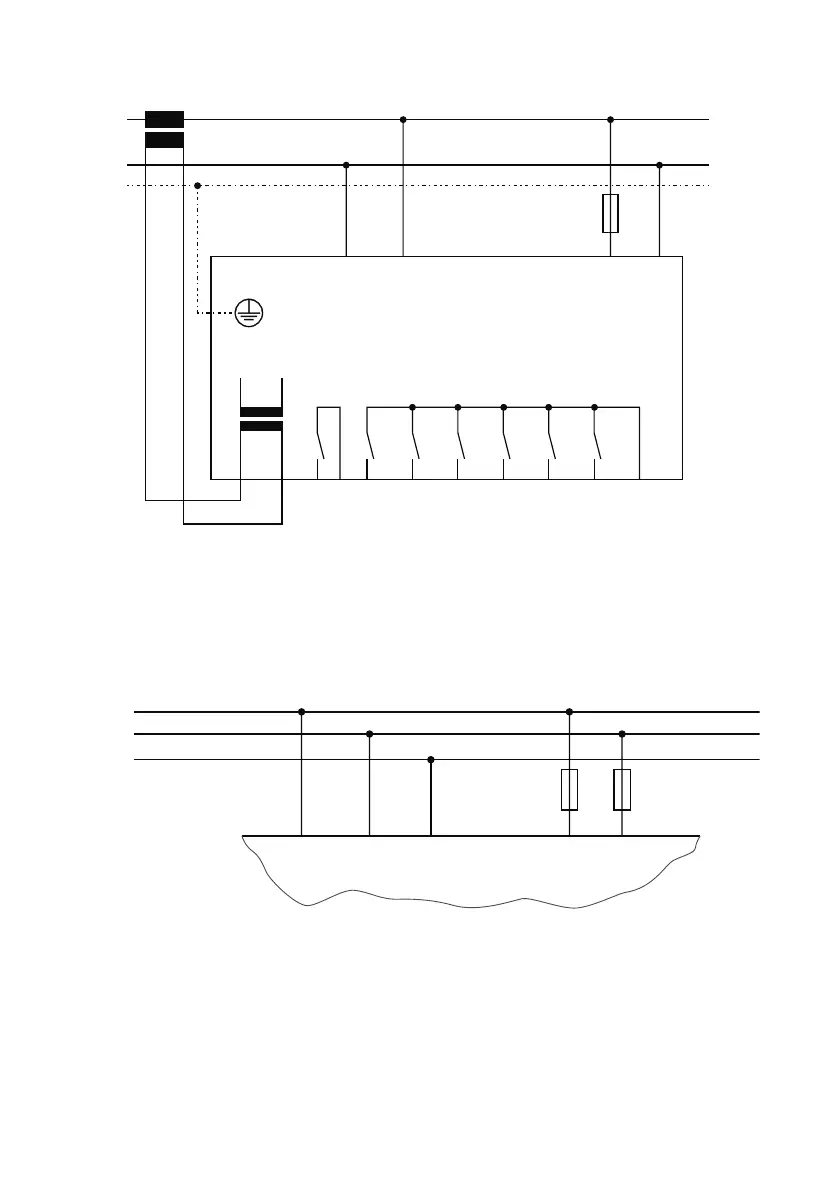
5.2.10.6 Connection diagram: Type PQC 0614801-xx
max.6A
N
ba
L/NL L/NL
2A T
AUX
S2S1
L
max.10 A
Alarm
Q1
Q6
Q5
Q4
Q3
Q2
P
Ausgangsrelais
output relays
440VAC~ 3A cos
φ =1 VDE
250VAC~ 3A cos
φ =1 VDE
Alarmrelais
alarm relays
250VAC~ 3A cos
φ =1
Versorgungsspannung
supply voltage
100V-15% – 480V+10% AC~5 VA
Messspannung
voltage measurement
100V– 690VAC~ VDE
100V– 600VAC~ UL
5.2.10.7 Options for connecting the AUX power supply for
PQC xxx480x-xx types
Connecting the AUX terminals to a 100 to 480 V AC power supply
Part of connection diagram for 400/415 V networks with no neutral conductor
N
L2
N
L3
L1
L2L1 L3 L/NL
2A T
PQC
AUX
2A T
L2
L3
L2L1 L3 L/NL
2A T
PQC
AUX
Instrument type: PQC xxx480x-xx
400 V AC / 415 V AC – Networks with no neutral N