34 | Installation
Power Quality Controller – PQC | Operating Manual | FRAKO
V = network voltage in V at the primary side of the voltage transformer
k = transformer ratio (primary side / secondary side)
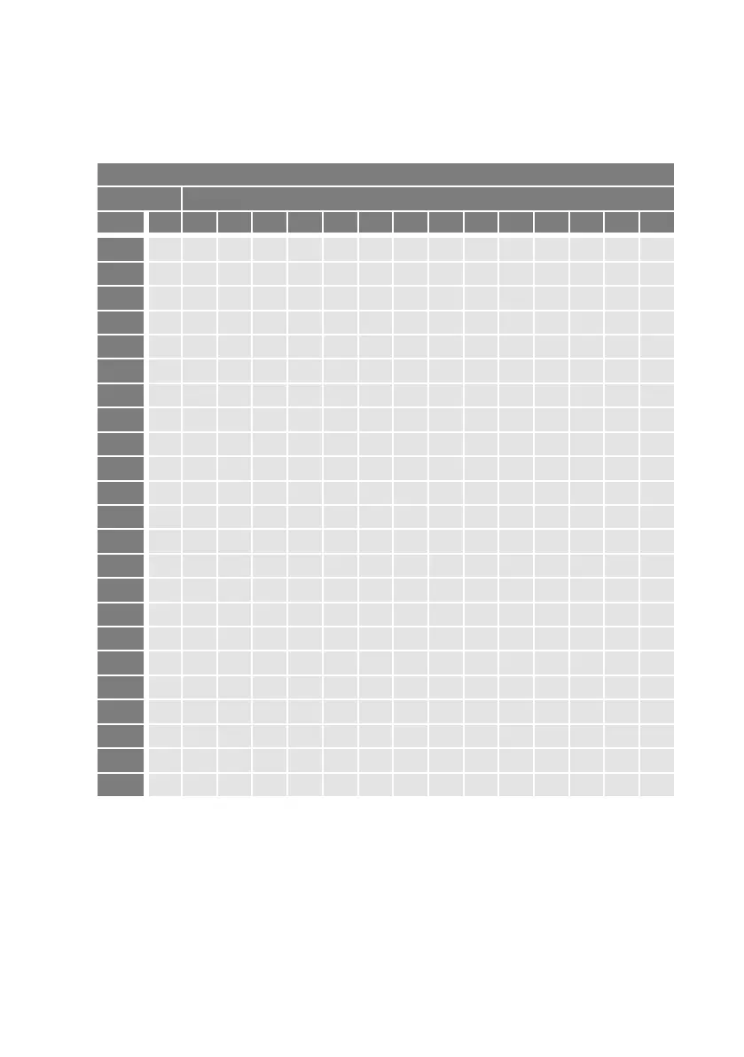
Alternatively, for a 400 / 50 Hz network the c/k setting can also be read off from the
table below:
c/k setting for 400 V 50 Hz AC network ~
Current Stage power (not total power) of the PF correction system in kvar
k 2.5
5 6.25 7.5 10 12.5 15 20 25 30 40 50 60 100
30/5 6 400 800 980 1200 1600
40/5 8 300 600 740 900 1200 1500
50/5 10 240 480 590 720 960 1200 1440
60/5 12 200 400 490 600 800 1000 1200 1600
75/5 15 160 320 390 480 640 800 960 1280 1600 1920
100/5 20 120 240 300 360 480 600 720 960 1200 1440 1920
150/5 30 80 160 200 240 320 400 480 640 800 960 1280 1600 1920
200/5 40 60 120 150 180 240 300 360 480 600 720 960 1200 1440
250/5 50 50 100 120 140 190 240 290 380 480 580 770 960 1150 1920
300/5 60 40 80 100 120 160 200 240 320 400 480 640 800 960 1600
400/5 80 30 60 80 90 120 150 180 240 300 360 480 600 720 1200
500/5 100 20 50 60 70 100 120 140 190 240 290 380 480 580 960
600/5 120 40 50 60 80 100 120 160 200 240 320 400 480 800
750/5 150 30 40 50 60 80 100 130 160 190 260 320 380 640
1000/5 200 20 30 40 50 60 70 100 120 140 190 240 290 480
1500/5 300 20 20 30 40 50 60 80 100 130 160 190 320
2000/5 400 20 30 40 50 60 70 100 120 140 240
2500/5 500 20 30 40 50 60 80 100 120 190
3000/5 600 20 30 40 50 60 80 100 160
4000/5 800 20 30 40 50 60 70 120
5000/5 1000 20 30 40 50 60 100
6000/5 1200 20 30 40 50 80
7000/5 1400 20 30 40 70