60 | Description of the menu
Power Quality Controller – PQC | Operating Manual | FRAKO
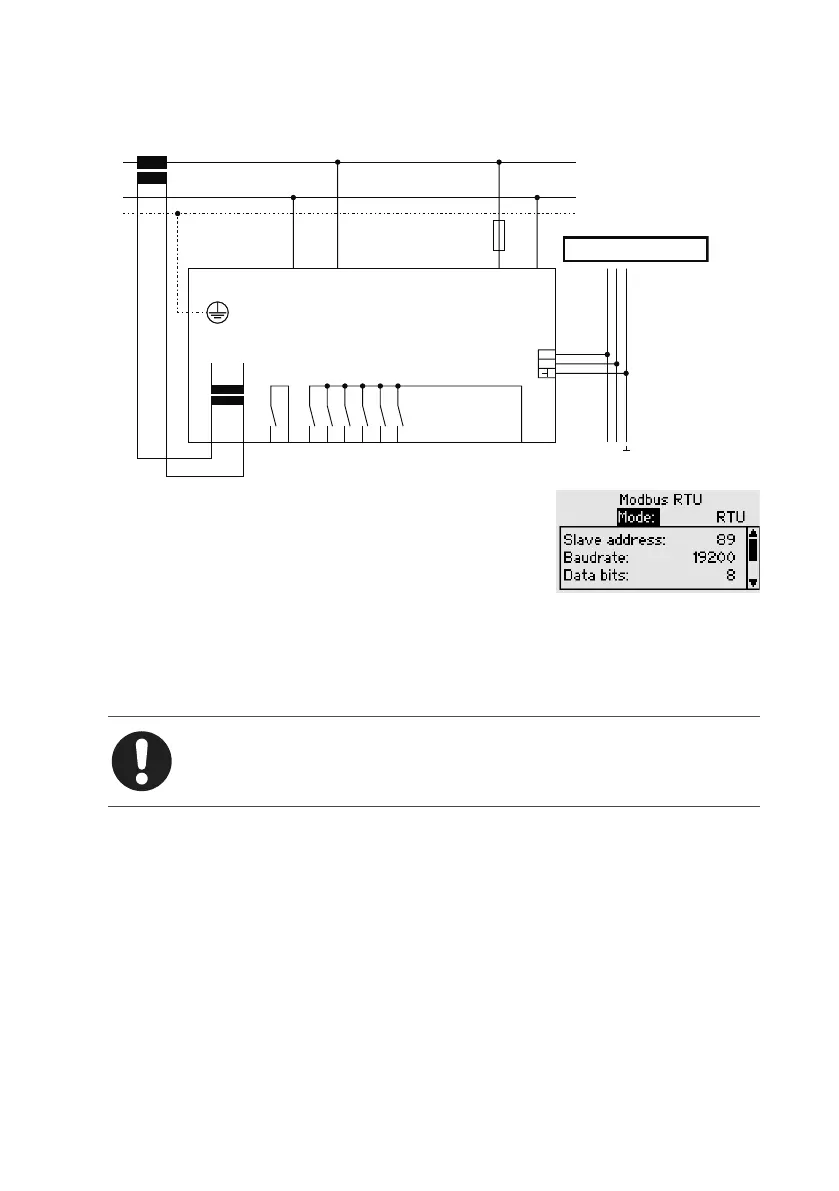
6.3.5.1 Modbus RTU
Modbus RTU connection
max.6A
N
ba
L/NL L/NL
2A T
AUX
S2S1
L
max.10A
Alarm Modbus RTU
Q1
Q6
Q5
Q4
Q3
Q2
P
Ausgangsrelais
output relays
250VAC~ 3A cos
φ =1
Alarmrelais
alarm relays
250VAC~ 3A cos φ =1
Versorgungsspannung
supply voltage
100V-15% – 240V+10% AC~5VA
Messspannung
voltage measurement
100V–690VAC~ VDE
BA
A B
A
≙
R×D/T×D-N Datenleitung-Minus (-)
B
≙
R×D/T×D-P Datenleitung-Plus (+)
Versorgungsspannung
supply voltage
100V-15% – 240V+10% AC~5VA
The following parameters can be set in the Modbus con-
figuration menu:
Bus address The PQC is accessed at the set
bus address
Baud rate 1200, 2400, 4800, 9600, 19200,
38400, 57600, 115200
Data bits 5 to 8
Stop bits 1 or 2
Parity even, odd or none
Note
Further details are described in the Modbus Specification.