Description of the menu | 63
FRAKO | Operating Manual | Power Quality Controller – PQC
If a defined alarm limit is to be monitored with each tem-
perature measurement input, these can be set in the PQC
Alarms menu (see Section 6.3.4 “Alarms”). A fixed hyster-
esis of 1.5 K is programmed.
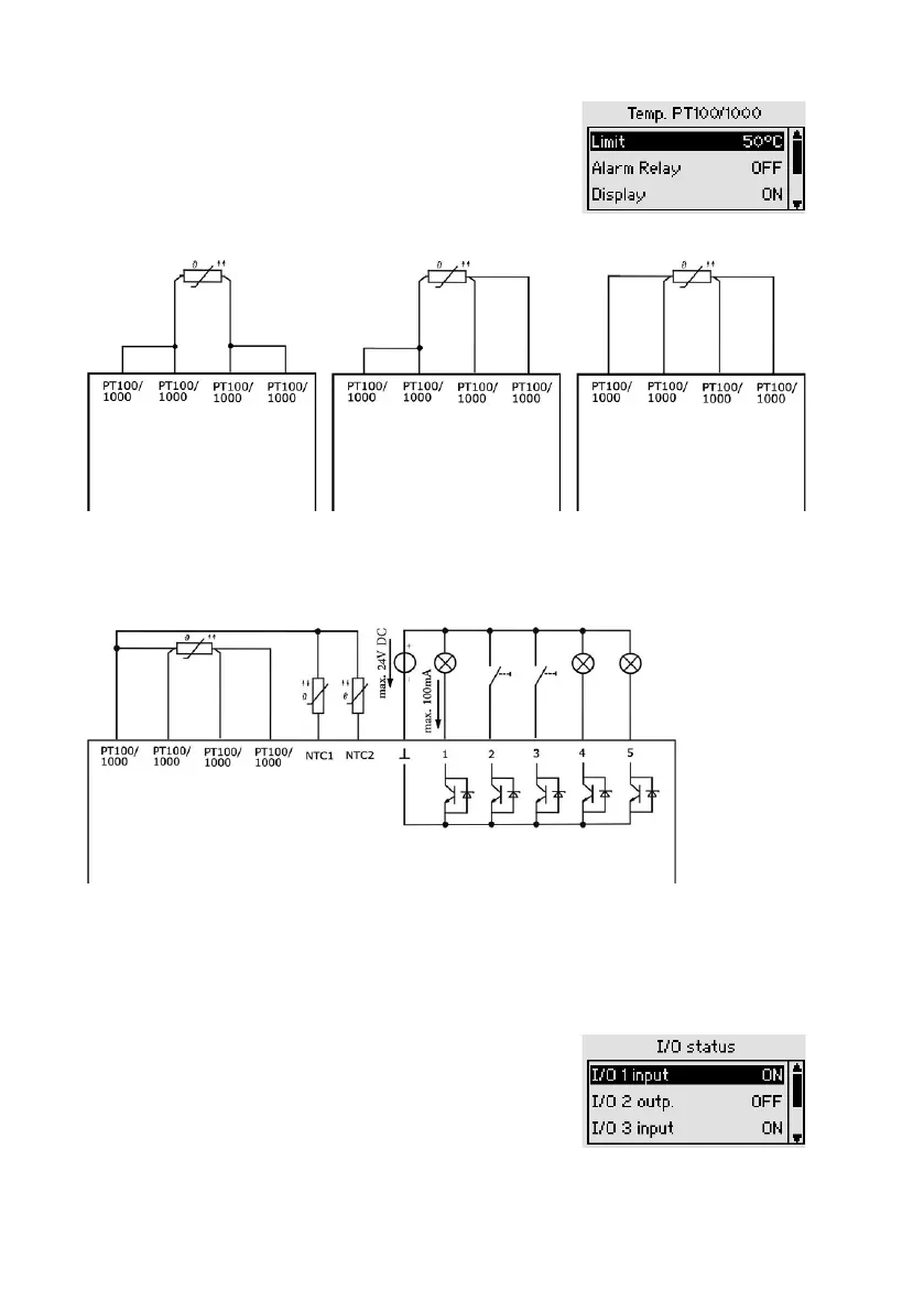
Connections for a PT-100 / 1000 temperature measure-
ment input are provided:
2-wire connection 3-wire connection 4-wire connection
In addition, one or two 2-wire NTC probes (Article No. 29-20094, 7-metre cable) can
be connected as shown below:
Passive digital inputs and outputs
The terminals 1 to 5 can be configured for the particular application as inputs or out-
puts in the PQC: Main menu > Parametrization > Temp. I/O (dyn.). If the configured
inputs or outputs as used as alarms, the alarm routes can be set in the Alarms menu
(see Section 6.3.4 “Alarms”).
The momentary statuses of the inputs and outputs are
shown in the I/O Status menu (see Section 6.2.3.6
“Temperatures (optional temperature I/O extension)”).