Franka Emika GmbH ©October 2018
57
The Arm is equipped with highly sensive sensor technology and ne-tuned con-
trol algorithms. The Control algorithm requires installaon on a stable, non-mov-
ing and non-vibrang plaorm.
In parcular, the following maximum forces must be supported during stac and
dynamic operaon:
• vercal force: 410 N
• horizontally force: 300 N
• lng torque: 280 Nm
• torque around axis 1: 90 Nm
The Arm has to be connected to the baseplate with 4 screws sized accordingly.
For this purpose, 4 drill holes with a diameter of 9mm are provided in the base
ange of the Arm. The screw connecon must be suitable for withstanding the
stac and dynamic forces generated.
Example for possible screw connecon:
• thickness of baseplate: 20mm
• 4x cylindrical head screw with hexagon socket M8x25mm – strength class 8.8
• 4x washer M8
• ghtening torque for screws 23 Nm
• Note that aer 100 hours of operaon the screws need to be ghtened again
with the ghtening torque indicated!
Stable plaorm
WARNING
If the Arm is installed on moving, instable ground, this may cause malfunctions
and unexpected movements of the robotic arm or cause it to fall. This may lead
to severe injuries.
Therefore:
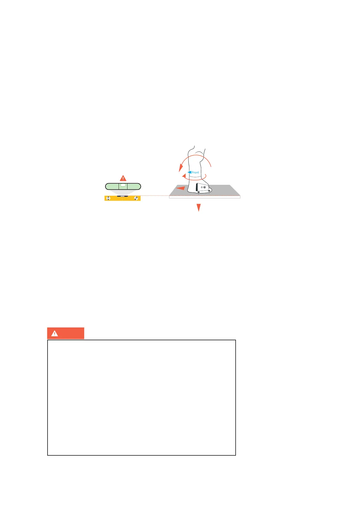
• always install the Arm so that its base is horizontal to the earth’s surface
• the Arm may not be installed hanging
• the platform of the Arm must be stable
• the platform may not move, vibrations are not permissible
• When used in earthquake-prone areas this needs to be considered
during the risk assessment.
• the screw connection must be laid out correctly and must hold tight
• after 100 hours of operation the screws need to be tightened again
with the tightening torque indicated!
Screw connecon to baseplate
vercal force
horizontal force
torque around axis 1
lng torque