TCA200 Rev171031
6
GENERAL DESCRIPTION
All controls and indicators are located on the front of the control module.
Components
The pressure governor and instrument panel consist of the following components:
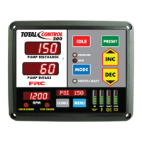
Control Module
Intake Pressure Sensor
Discharge Pressure Sensor
Audible Alarm Buzzer
Cables
Control Module
The control module is waterproof and takes up 7 1/2 by 6 inches of panel space. All
controls, indicators, and displays are located on the front of the control panel. (Refer
to Controls and Indicators.)
Intake Pressure Sensor
The pressure sensor is mounted on the pump intake manifold. It provides an input
signal to the control module that is proportional to the intake pressure.
Discharge Pressure Sensor
The pressure sensor is mounted on the pump discharge manifold. It provides an
input signal to the control module that is proportional to the discharge pressure.
Audible Alarm Buzzer
A ground is provided at the 8-pin connector pin 2 to activate the buzzer (max
current: 300mA).