Do you have a question about the FRC TotalControl 200 and is the answer not in the manual?
Provides a general description of the governor's functions, modes, and displays.
Lists the key operational and functional characteristics of the governor.
Details power supply, current draw, physical dimensions, and measurement units.
Specifies the operating ranges for engine oil, coolant, transmission, and battery voltage.
Outlines model numbers, pressure ranges, proof pressure, and output voltage.
Lists the main parts of the pressure governor system including the control module and sensors.
Explains the role of pressure sensors and the activation of the audible alarm buzzer.
Explains how to activate and use the high idle feature.
Describes connector types and wiring for system integration.
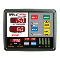
Describes the Pump Discharge, Pump Intake, and Message displays.
Details the MODE, IDLE, PRESET, and INC/DEC buttons.
Explains the function of RPM, PRESSURE, VOLTS, TRANS, ENG, OIL LEDs.
Details the MENU, SILENCE, and STOP ENGINE/CHECK ENGINE buttons.
Describes the RPM Display and THROTTLE READY LED.
Provides steps for mounting the control module and connecting cables.
Details how to install the intake and discharge pressure sensors.
Explains how to use INC/DEC, MODE, MENU, SILENCE, and PRESET buttons.
Explains valve operation in pressure mode.
Describes intake valve operation from a pressurized source.
Describes governor response to low water and running away from water.
Details governor response to low and no water supply.
Explains how to operate the governor in RPM mode, including pressure limits.
Explains how to switch between pressure and RPM modes.
Describes managing high discharge pressure when the engine is at idle.
Describes how to access and view detailed operational data.
Instructions for setting and changing pre-programmed pressure or RPM values.
Details how to activate and adjust the high idle setting.
Covers viewing revision numbers, manufacturing dates, and setting current date.
Details how to set the current time and retrieve fault codes.
Explains how to enter the calibration password and access programs.
Details the self-calibration process for pressure sensors C1 and C2.
Details the pin assignments for the 12-pin and 8-pin connectors.
Shows the overall interface wiring for the control module.
Specifics on connecting the pressure sensor cable.
Describes common OEM diagnostic connectors.
Details DDEC III ECU connections.
Details DDEC IV, V, and VI series ECU connections.
Provides the wiring schematic for the high idle function.
Explains the purpose and installation of flyback diodes with inductive loads.
Outlines user responsibilities for safe operation and equipment maintenance.
| Resolution | 1600 x 900 |
|---|---|
| Response Time | 5 ms |
| Ports | VGA, DVI |
| Aspect Ratio | 16:9 |
| Brightness | 250 cd/m² |
| Contrast Ratio | 1000:1 |
| Weight | 3.5 kg |
| Screen Size | 20 inches |
| Viewing Angle | 170°/160° |