Let us learn how connection mode of common anode works. Choose 16 ports on RPI board to connect to the
16 ports of LED Matrix. Configured one port in columns for low level, which make the column of the port
selected. Then configure the eight ports in row to display content in the selected column. Delay for a moment.
And then select the next column and outputs the corresponding content. This kind of operation to column is
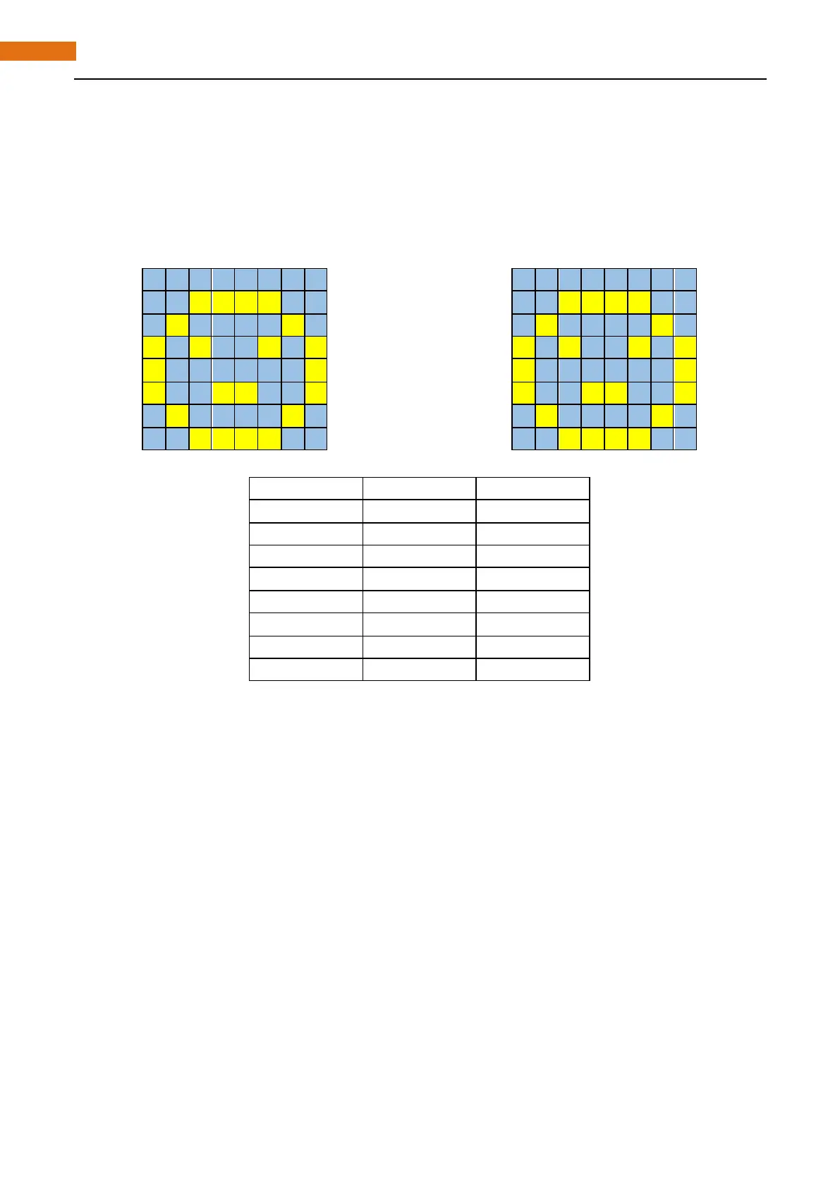
called scan. If you want to display the following image of a smiling face, you can display it in 8 columns, and
each column is represented by one byte.
First, display the first column, then turn off the first column and display the second column...... turn off the
seventh column and display the 8th column, and then start from the first column again like the control of
Graph LEDBar. The whole progress will be repeated rapidly and circularly. Due to afterglow effect of LED and
visual residual effect of human eyes, we will see a picture of a smiling face directly rather than LED are turned
on one column by one column (although in fact it is the real situation).
Scanning rows is another display way of dot matrix. Whether scanning line or column, 16 GPIO are required.
In order to save GPIO of control board, two 74HC595 is used. Every piece of 74HC595 has eight parallel output
ports, so two pieces has 16 ports in total, just enough. The control line and data line of two 74HC595 are not
all connected to the RPi, but connect Q7 pin of first stage 74HC595 to data pin of second one, namely, two
74HC595 are connected in series. It is the same to using one "74HC595" with 16 parallel output ports.