QUANTUM™ HD UNITY SYSTEM CONTROLLER
MAINTENANCE
090.670-M (APR 2020)
Page 15
Q5 Processor Board Jumpers, LEDs, and Connectors
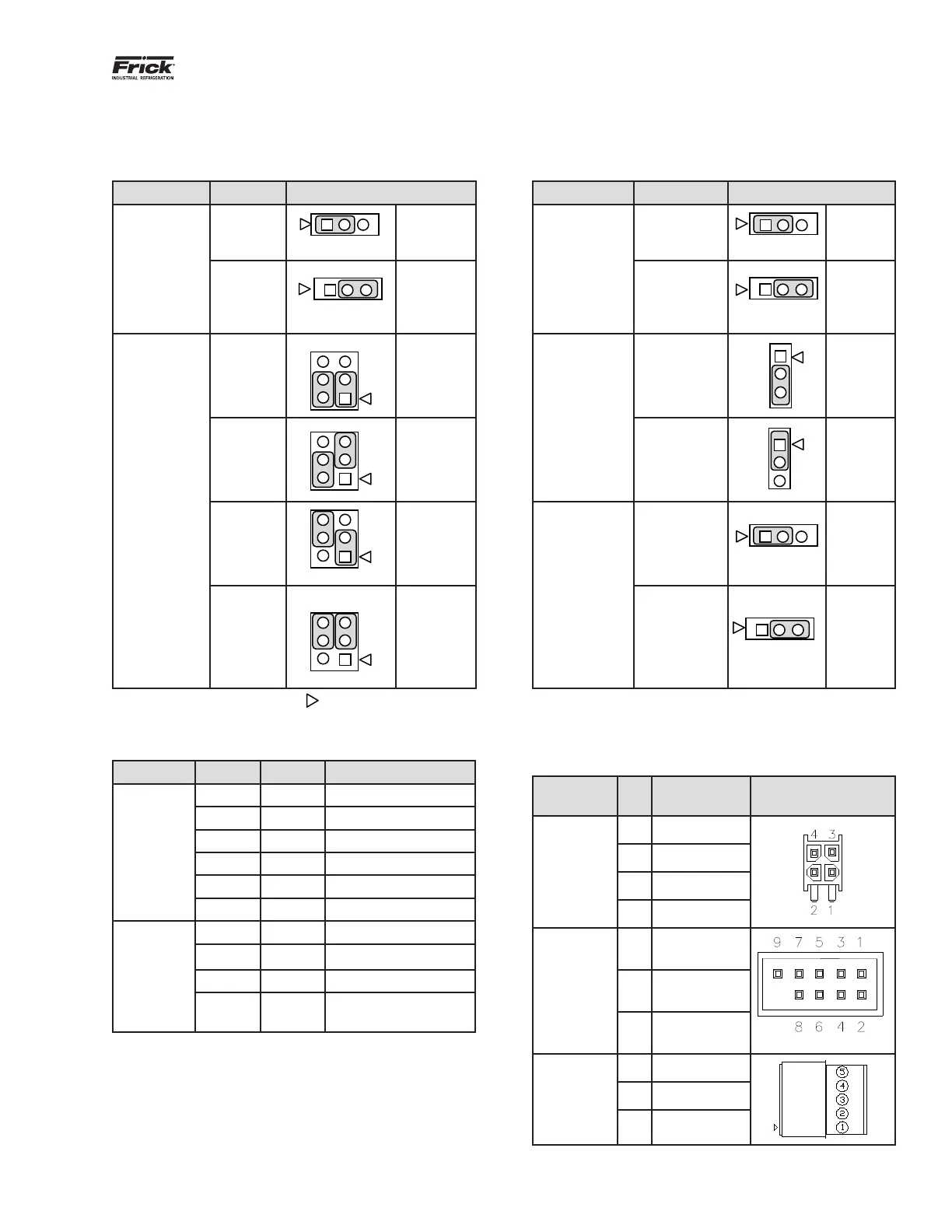
Table 1: Jumper table
Jumper title Function Jumper setting Jumper title Function Jumper setting
CMOS1
(CMOS Clear)
Normal
(default)
1 - 2
Closed
CN3
(Touch Panel
Type Selector)
5-Wire
Touch
Screen
1-2
Closed
Clear
CMOS
2 - 3
Closed
8-Wire
Touch
Screen
(default)
2-3
Closed
CN1000
(LCD Resolu-
tion Selector)
24-bit
800x600
6
4
2
5
3
1-3 Closed
&
2-4 Closed JLVDS2
(Backlight
Level Selec-
tor)
0 – 5V
(default)
2-3
Closed
24-bit
1024x768
(default)
6
4
3
3-5 Closed
&
2-4 Closed
0 – 2.5V
3
1-2
Closed
18-bit
800x600
6
4
3
1-3 Closed
&
4-6 Closed
JLVDS3
(Backlight
Control Mode)
Voltage
Mode - use
with inverter
1-2
Closed
18-bit
640x480
6
4
2
5
3
3-5 Closed
&
4-6 Closed
PWM Mode
(Use for LED
display - no
inverter)
(default)
2-3
Closed
Note 1: The triangle symbol (
) denotes Pin 1 on connectors.
Note 2: Jumper CN4 is not shown on this chart, as it must always be installed.
Table 2: Q5 LED denition table
LED title Label Color Function
Power
LED’s
LED1 Red 5VSB
LED2 Red 3VSB
LED3 Green VCC 12V
LED4 Green VCC 5V
LED5 Green VCC 3V
LED6 Blue Power On OK Status
Ethernet
LEDs
1000MB Green Giga – LAN Speed
100MB Yellow 100MB - LAN Speed
10MB Red 10MB –LAN Speed
ACT
Green
(Blinks)
LINK Activity
Table 3: Q5 Connector pinout table
Connector
title
Pin Function
CN_PWR1
(Power
Input)
1 Ground (GND)
2 Ground (GND)
3 VCC 12V
4 VCC 5V
COM1 and
COM2
(RS-232
Communi-
cations)
2 Receive (RX)
3 Transmit (TX)
5 Ground (GND)
COM3 &
COM4
(RS-485
Communi-
cations)
1 -RX/TX
2 +RX/TX
3 Ground (GND)