QUANTUM™ HD UNITY SYSTEM CONTROLLER
MAINTENANCE
090.670-M (APR 2020)
Page 16
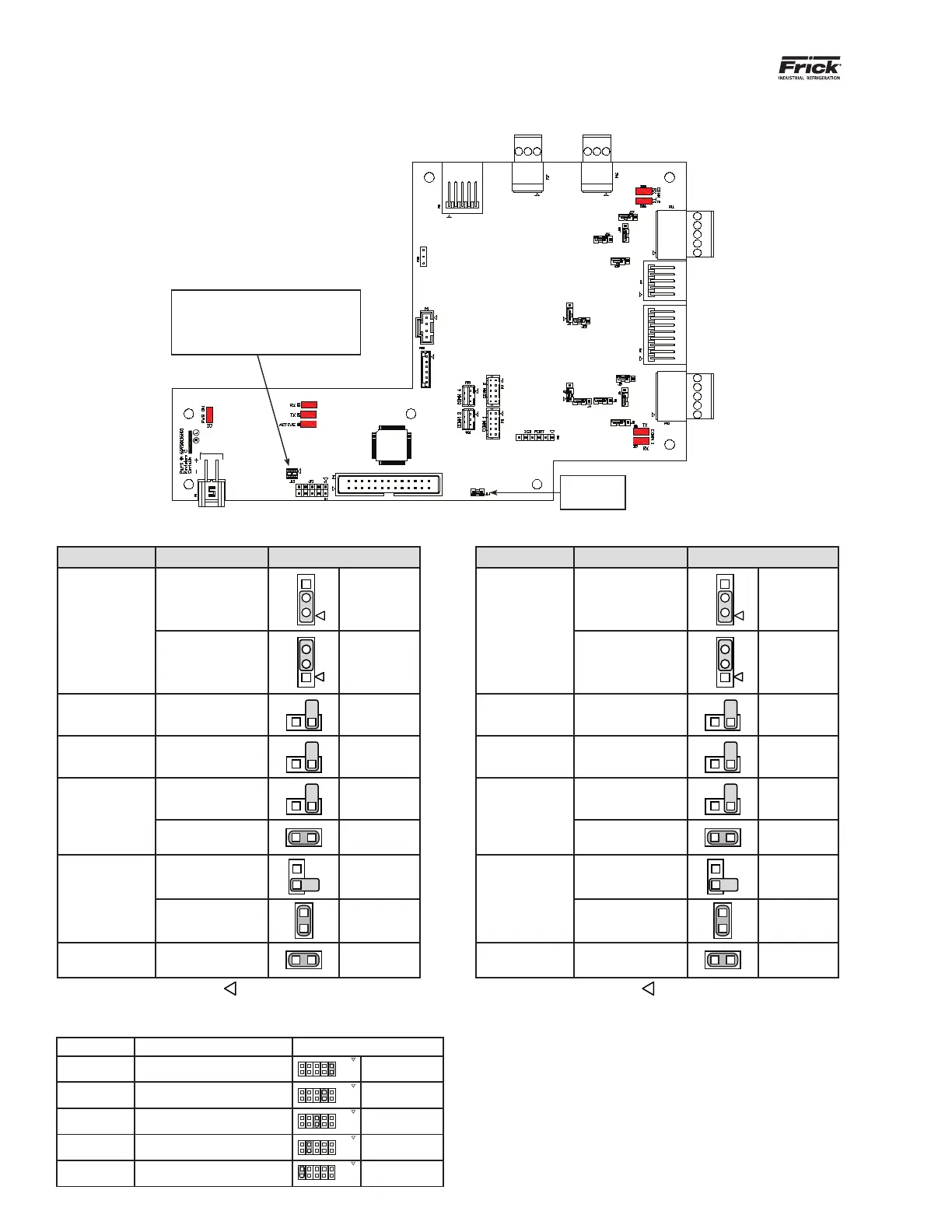
Figure 7: Q5 interface board diagram
Do Not
Remove J14
Baud Rate Jumpers
J15 Not Installed = 19200 (Default)
J15 Pins 1-2 Installed = 38400
J15 Pins 3-4 Installed = 56K
J15 Pins 1-2 and 3-4 Installed = 115K
COMM
4
COMM
3
COMM
2
COMM
1
Table 4: Comm 1 jumper settings
Table 5: Comm 2 jumper settings
Jumper title Function Jumper setting
J1
RS-422 (4-Wire)
Default
1
1 - 2 Closed
RS-485
(2-Wire)
2
1
2 - 3 Closed
J2
Pull Down
Default
1 Pin Only
J3
Pull Up
Default
1 Pin Only
J5
RS-422
Default
1 Pin Only
RS-485 1 - 2 Closed
J6
RS-422
Default
1 Pin Only
RS-485
1 - 2 Closed
J4
High Speed Target
Default
1 - 2 Closed
Jumper title Function Jumper setting
J7
RS-422 (4-Wire)
Default
1
1 - 2 Closed
RS-485
(2-Wire)
2
1
2 - 3 Closed
J13
Pull Down
Default
1 Pin Only
J16
Pull Up
Default
1 Pin Only
J17
RS-422
Default
1 Pin Only
RS-485 1 - 2 Closed
J18
RS-422
Default
1 Pin Only
RS-485
1 - 2 Closed
J22
High Speed Target
Default
1 - 2 Closed
Jumper JP1 Function Jumper Setting
1 - 2 Not Used
Not Installed
3 - 4 Reformat E2Prom Installed
5 - 6 Erase Setpoints (at boot-up) Installed
7 - 8 Reset IP Address Installed
9 - 10 Disable Watchdog Installed
Note: The triangle symbol (
) denotes Pin 1 on connectors. Note: The triangle symbol (
) denotes Pin 1 on connectors.
Table 6: JP1 system settings