QUANTUM™ HD UNITY SYSTEM CONTROLLER
MAINTENANCE
090.670-M (APR 2020)
Page 18
Power Supplies
Description
Three power supplies are used in the Quantum HD Unity
System Controller:
+5 VDC (25W/5A) 5.1 VDC to 5.2 VDC
+12 VDC (72W/6A) 12.2 VDC to 12.5 VDC
+24 VDC (72W/3A) 24.2 VDC to 24.6 VDC
The 5 VDC is used primarily for the digital boards.
The 12 VDC is used primarily for the processor and interface
boards. The display is powered from the processor board.
The 24 VDC is primarily used for the analog boards, ether-
net switch, and other ancillary items.
It may be necessary to add additional power supplies for
system components so as to not overload these power
supplies.
Figure 9: 5 V, 12 V, and 24 V power supplies
Measuring voltages
CAUTION
Measuring and adjusting the power supply volt-
age requires the control power switch to be ener-
gized. Extreme care must be observed when taking
any readings, as 120 VAC or 230 VAC (depending on
incoming system voltage) will be present next to the
DC voltage connector.
Adjusting the supply requires the use of a small Phillips
screwdriver inserted into the supply to access an adjusting
potentiometer. Note that the tip and shaft of the screw-
driver must be non-metallic.
WARNING
It is possible for the screwdriver, and the person
making the adjustment, to come into contact with
potentially lethal voltages. Proper Personal Protective
Equipment (PPE) measures need to be observed.
All circuit boards within the Quantum HD Unity System
Controller require accurately adjusted DC voltages in order
to function properly. Periodically measure and adjust the
DC power system for optimum system operation. Over
time, it is possible for temperature, humidity, vibration,
and component age, to degrade the accuracy of these
voltages. When any of the DC voltages begin to stray from
their optimum range, abnormalities or problems may arise.
To perform measurements and adjustments on the power
supply voltage, use a reliable, calibrated digital volt meter
(DVM). Check the voltage only after the controller is fully
booted and the System Overview page is viewable. If the
screen never appears however, possibly due to a voltage
problem, you need to proceed regardless of what is or is
not displayed.
In order to properly measure the DC power system, rst
check at the DC power supply.
Adjustment
Ensure that the meter is set to the proper range (DC,
0 V to 50 V or equivalent), as well as observing proper
wire polarity. The power supply image shown below ap-
plies to all three power supplies. The adjustment access
hole for each supply is located on the lower left of the
front of the supplies. If an adjustment is required, use a
thin Phillips screwdriver and insert the tip into the access
hole for the appropriate voltage potentiometer. See the
power supply image for adjustment location.
NOTICE
Extreme care must be used when adjusting the po-
tentiometer. Adjustment should only be performed by
qualied personnel. Use a non-conductive device.
The 24 VDC power supply is the same as the 12 VDC
power supply with regard to terminal location, test point,
and adjustment potentiometer
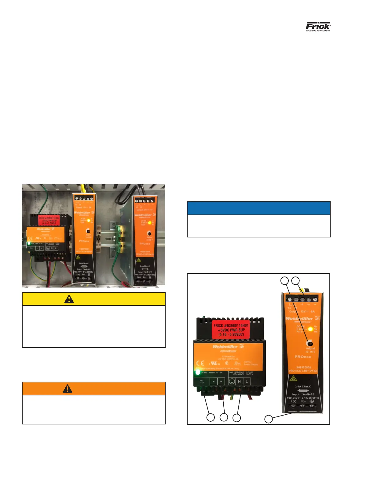
Figure 10: 5 V and 12 V power supplies
A
A
B
B
C
D
A. Adjustment Potentiometer
B. DC Voltage Out +/-
C. AC Voltage In (G,N & L)
D. AC Voltage In (L,N & G)
Power supply replacement
If the power supply is found to be bad, or not capable of
acceptable adjustment, the failing supply needs replace-
ment. See the Replacement Parts section for the appropri-
ate part number.