QUANTUM™ HD UNITY SYSTEM CONTROLLER
MAINTENANCE
090.670-M (APR 2020)
Page 48
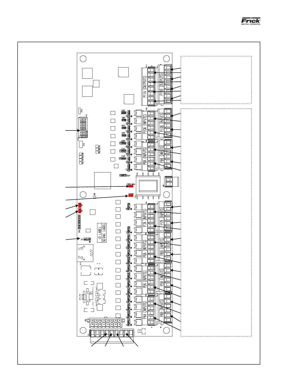
Figure 35: Engine room analog board 1
CH24 – OPEN INPUT
CH22 – OPEN INPUT
CH23 – OPEN INPUT
CH21 – OPEN INPUT
CH20 – OPEN INPUT
CH18 – OPEN INPUT
CH19 – OPEN INPUT
CH17 – OPEN INPUT
CH16 – OPEN INPUT
CH14 – OPEN INPUT
CH15 – OPEN INPUT
CH13 – OPEN INPUT
CH12 –
Underfloor Temperature D
CH10 – Underfloor Temperature B
CH11 – Underfloor Temperature C
CH9 – Underfloor Temperature A
CH8 – Underfloor Glycol Supply Temp.
CH6 – Refrigerant Detector D
CH7 – Underfloor Glycol Return Temp.
CH5 – Refrigerant Detector C
CH4 – Refrigerant Detector B
CH2 – OPEN INPUT
CH3 – Refrigerant Detector A
CH1 – Engine Room Temperature
OUTPUTS
CH8 – Auxiliary Output (P/I Control)
CH4 – VSD Ventilation Fan D
CH7 – Auxiliary Output (P/I Control)
CH3 – VSD Ventilation Fan C
CH6 – Auxiliary Output - P/I Control B
CH2 – VSD Ventilation Fan B
CH5 – Auxiliary Output - P/I Control A
CH1 – VSD Ventilation Fan A
COM +Tx/+Rx +24VDC-Tx/-Rx
SW1
PWR OK LED (D65)
Active LED (D64)
Tx LED (D62)
Rx LED (D63)
J33 Defaulted Pins 2-3



 To Next Page