56 PB
Determining the Indoor CFM
Model VRP07K/ VRP07R
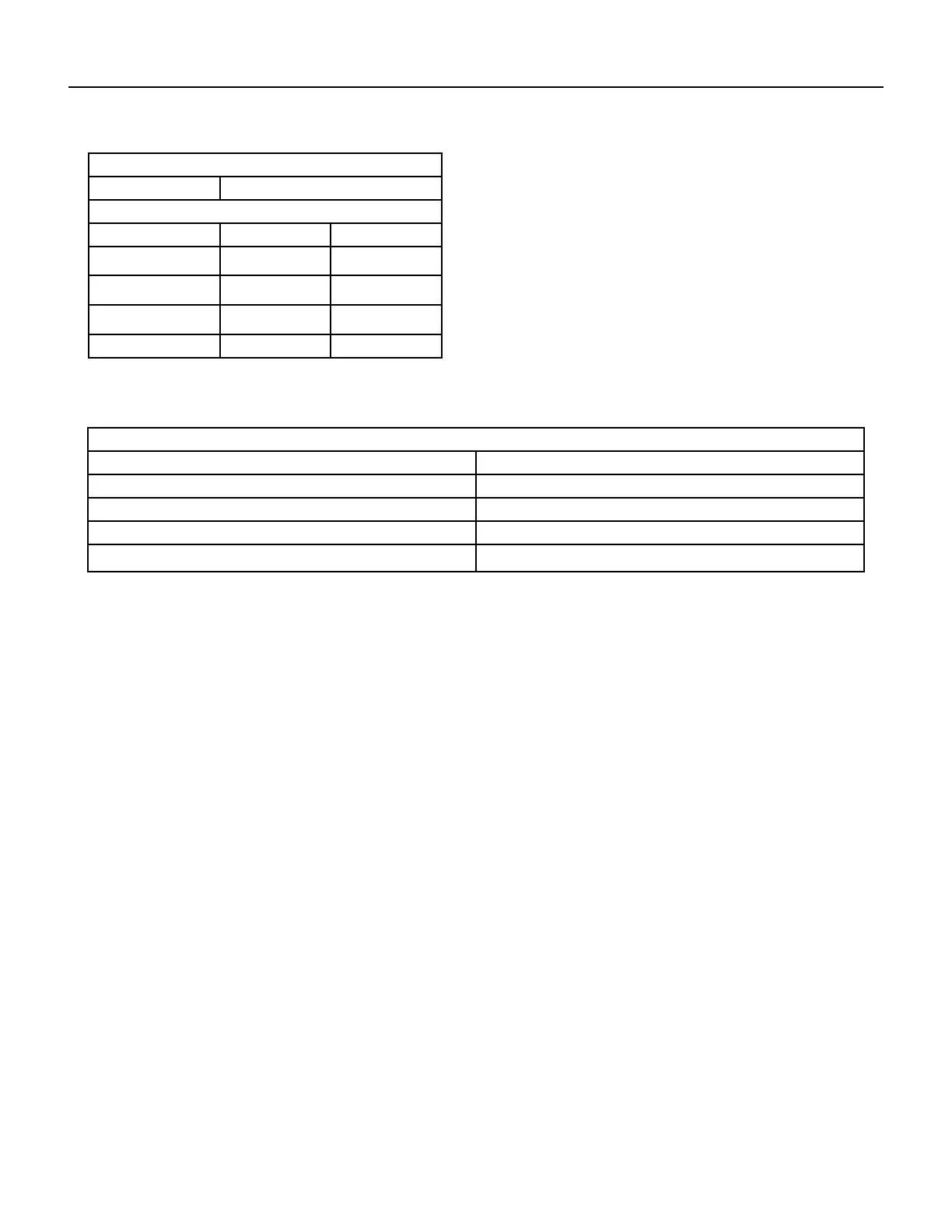
Air Flow Data
Indoor CFM LOW HIGH
.05” ESP* 300 360
.1O ESP* 260 335
.15” ESP (MAX LOW) 230 315
.20” ESP - 290
* Rated at 0.10” ESP, High and includes 0.08” ESP for factory installed 1” filter
Table XXX (determining Indoor CFM)
Correct CFM (if needed): Correction Multipliers
230V 1.00
208V 0.97
265V
Heating 1.00
Cooling 0.95
Explanation of charts
Chart A is the nominal dry coil VRP CFMs. Chart B is the correction factors beyond nominal conditions.
Operating on high speed @ 230 volts with dry coil
measured external static pressure .10
Air Flow = 450 CFM
In the same SYSTEM used in the previous example but having a WET coil you must use a correction factor of .95 (i.e. 450 x .95=428
CFM) to allow for the resistance (internal) of the condensate on the coil.
It is important to use the proper procedure to check external Static Pressure and determine actual airfl ow. Since in the case of the VRP,
the condensate will cause a reduction in measured External Static Pressure for the given airfl ow.
It is also important to remember that when dealing with VRP units that the measured External Static Pressure increases as the
resistance is added externally to the cabinet. Example: duct work, filters, grilles.
Indoor Airflow Data
The VRP A series units must be installed with a free return air configuration. The table below lists the indoor airflow at corresponding
static pressures. All units are rated at low speed.
The VRP units are designed for either single speed or two fan speed operation. For single speed operation refer to the airflow table
below and select the most appropriate CFM based on the ESP level. Connect the fan output from the thermostat to the unit on either the
GL terminal for low speed or to the GH terminal for high speed operation.
For thermostats with two‑speed fan outputs connect the low speed output to the unit GL terminal and the high speed output to the GH
terminal.
Ductwork Preparation
If flex duct is used, be sure all the slack is pulled out of the flex duct. Flex duct ESP can increase considerably when not fully
extended. DO NOT EXCEED a total of .30 ESP, as this is the MAXIMUM design limit for the VERT‑I‑PAK A‑Series unit.
IMPORTANT: FLEX DUCT CAN COLLAPSE AND CAUSE AIRFLOW RESTRICTIONS. DO NOT USE FLEX DUCT FOR: 90 DEGREE BENDS,
OR UNSUPPORTED RUNS OF 5 FT. OR MORE.
EXTERNAL STATIC PRESSURE