18
The keys are capacitive, and any exposure to water can impair their function. Wipe the
keys dry with a cloth if necessary to ensure optimum functionality.
Display Power for the display comes from the mains voltage. Depending on the setting selected in
the Setup menu, the display can be kept on all day.
IMPORTANT!
The display on the inverter is not a calibrated measuring device.
A slight inaccuracy in comparison with the energy meter used by the power supply compa-
ny is intrinsic to the system. A calibrated meter will be needed to calculate the bills for the
power supply company.
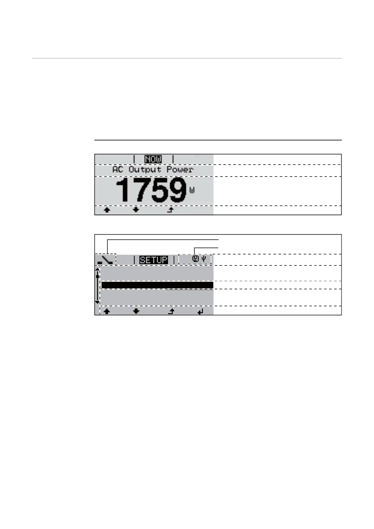
Display areas in Display mode
Display areas in Setup mode
(*) Scroll bar
(**) The Energy Manager symbol
is displayed when the Energy Manager function is activated
(***) Inv. no. = Inverter DATCOM number,
Save symbol - appears briefly while set values are being saved,
USB connection - appears if a USB flash drive has been connected
Function key functions
Menu item
Parameter declaration
Display of values, units and status codes
Function key functions
Next menu items
Currently selected menu item
Previous menu items
Menu item
Inv. no. | Save symbol | USB conn.(***)
(*)
1
Energy-Manager (**)
Standby
WiFi Access Point
DATCOM
USB
Relay