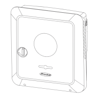
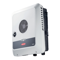
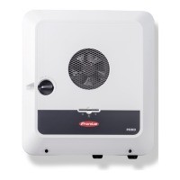
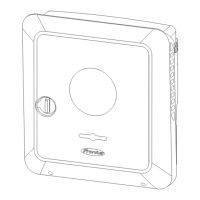
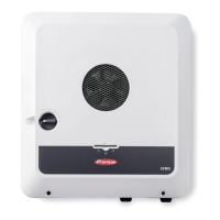
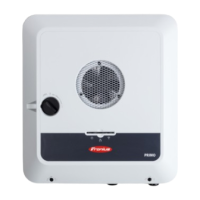
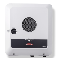
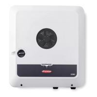
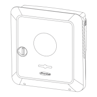
Manual switch to backup power 1-pin separation,
e.g. Australia / 2-pin separation, e.g. Germany
Functions
-
Measuring and transferring the required parameters for energy management
and Solar.web by the Fronius Smart Meter.
-
Monitoring of the grid parameters by the inverter.
-
Possibility of manual separation from the public grid if it fails or is deemed
unstable.
-
Option of having a separate backup power circuit or several backup power
circuits that are supplied even during failure of the public grid. The total load
of the backup power circuits must not exceed the rated power of the invert-
er. Furthermore, the performance of the connected battery must also be
considered.
-
If, in the event of a public grid failure, there is no manual switch to backup
power mode within the first 10 minutes, this may cause the inverter and the
battery to shut down. In order to then start backup power mode, manual
switching must take place and a manual system start must be performed, if
necessary (see chapter Manual system start on page 29).
-
It is possible to manually reconnect the inverter and loads in the backup
power circuit to the public grid once it is deemed to be stable again. The in-
verter only starts feed-in mode once the required grid monitoring time has
passed.
Transitioning
from feeding en-
ergy into the grid
to backup power
mode
1.
The public grid is monitored by the inverter's internal grid and system pro-
tection unit and by the Fronius Smart Meter connected to it.
2.
Failure of the public grid.
3.
The inverter carries out the measures necessary according to the country
standard and then switches off.
4.
The user switches the changeover switch Q1 from switch position 1 (grid op-
eration) via switch position 0 to switch position 2 (backup power mode). This
disconnects the backup power circuits and the inverter from the rest of the
home network and from the public grid. With all-pin separation, the ground
conductor and neutral conductor are additionally connected via the main
contacts of the switch. Switch position 2 (backup power mode) is reported
back to the inverter via a main contact of changeover switch Q1. In addition,
an interruption of the WSD line occurs when the changeover switch Q1 is
switched via switch position 0. This causes the inverter to shut down immedi-
ately. This behaviour is ensured via 2 contacts. Communication between the
inverter and Fronius Smart Meter is optionally interrupted via a contact. The
suspended communication prevents automatic termination of backup power
mode when the public grid returns, so that the inverter remains in backup
power mode until it is manually switched back.
5.
The inverter decides based on feedback for switch position 2 as well as the
measurements on the inverter terminals and the Fronius Smart Meter that
backup power mode can be started.
6.
After all the required activation tests have been carried out, the inverter
starts backup power mode.
7.
All loads in the backup power circuits are supplied with power. The remaining
loads are not supplied with power and are safely isolated.
52

 Loading...
