- Disconnecting devices must be mounted within sight and as close as possible to the
Fronius Smart Meter TS; they must also be easy to use.
- The disconnecting devices must satisfy the requirements of IEC 60947-1 and IEC
60947-3, as well as all national and local regulations for electrical systems.
- To monitor more than one mains voltage, use connected‑automatic circuit breakers.
- The overcurrent‑protection must protect the mains terminals with the designations
L1, L2 and L3. In rare cases, the neutral conductor has an overcurrent‑protection,
which must interrupt both neutral and non-earthed cables concurrently.
Auxiliary power
supply cabling
IMPORTANT!
An auxiliary power supply is required to operate the Fronius Smart Meter TS. The fuse
must match the dimensions of the conductors.
Cabling IMPORTANT!
Always switch off the power supply before connecting the mains voltage inputs to the
Fronius Smart Meter TS.
Recommended thickness of stranded mains voltage cables for the terminals of the
measuring input and measuring output:
- Wire: 1 - 4 mm²
- Recommended torque: max. 0.6 Nm
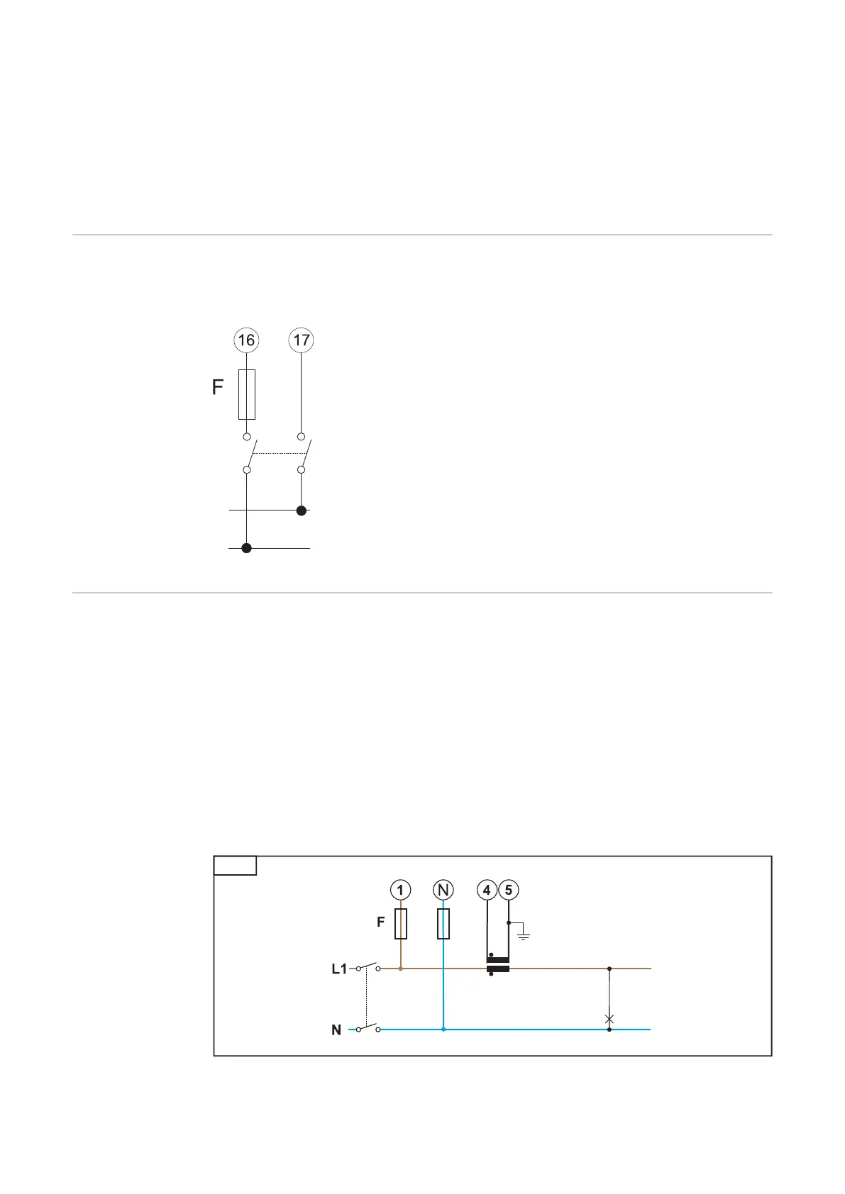
The measuring inputs of the current transformers must be earthed on one side as shown
in the circuit diagram.
Connect each voltage cable to the terminal strip as shown in the graphics below.
18

 Loading...


