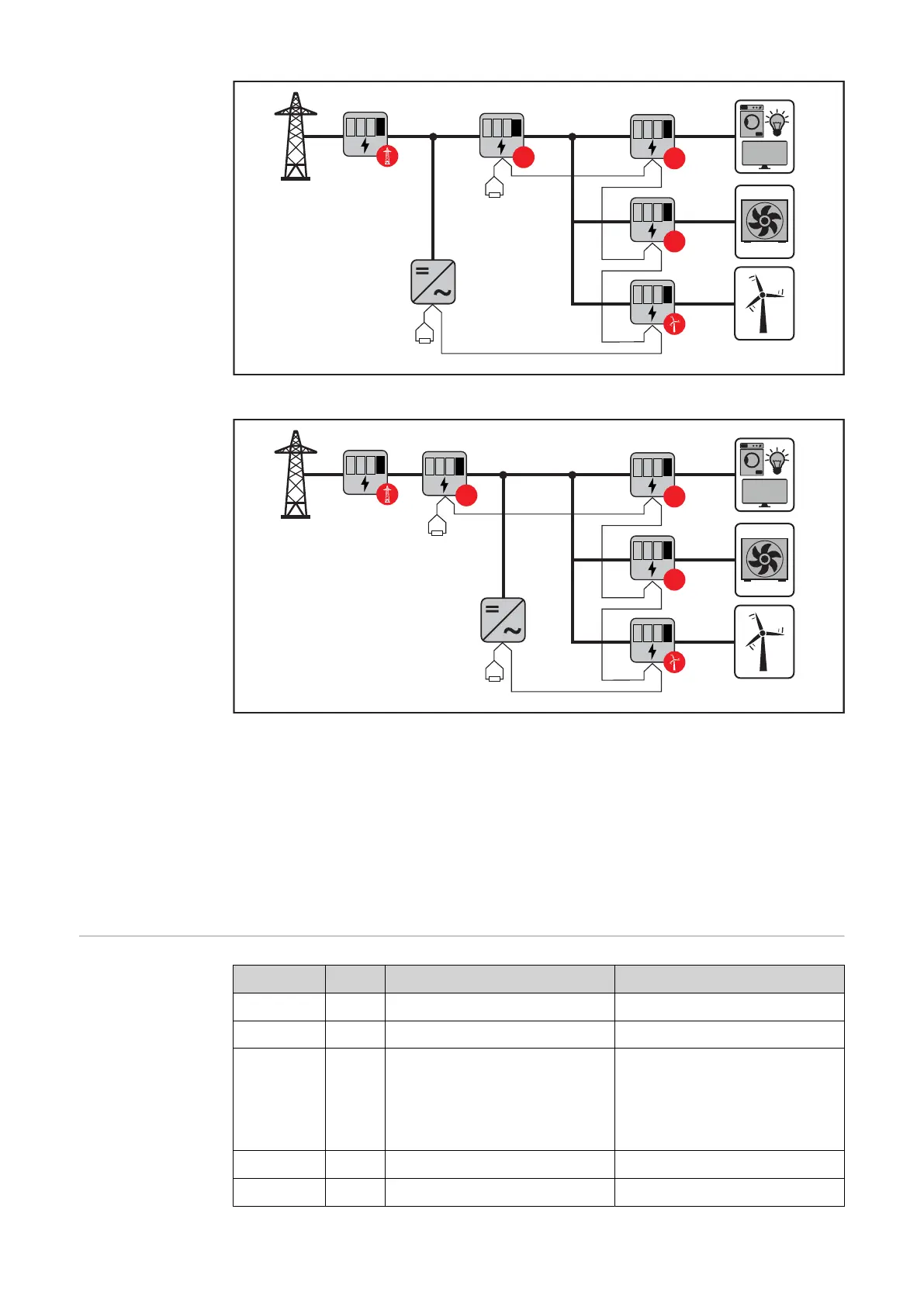
Location of the primary meter in the consumption branch. *Terminating resistor R 120 Ohm
Location of the primary meter at the feed-in point. *Terminating resistor R 120 Ohm
The following must be observed in a multi-meter system:
- Only assign each Modbus address once.
- Terminating resistors must be positioned individually for each channel.
For PV systems with inverters from the Fronius GEN24 and Fronius Tauro product
series, the following must be observed:
- The primary meter and the battery must be connected to different channels.
- The remaining Modbus participants must be distributed equally.
Parameters menu
Screen Code Description Values
PASS*** P1 Enter the current password 2633*
nPASS P2 Password change ** Four digits (0000-9999)
SYStEM P3 Type of system 3Pn*: three-phase system, 4-
core
3P: three-phase system, 3-
core
2P: two-phase system, 3-core
Ct rAtIo P4 Current transformer ratio from 1* to 1000
Ut rAtIo P5 Voltage transformer ratio from 1* to 1000
26

 Loading...


