5
The current transformers are connected to connections 4 and 5; 6 and 7; 8 and 9. If
necessary, excessively long cables can be shortened accordingly. Observe the
sequence in which the phases are connected. Accurate power measurement is only
ensured if the mains voltage phases match the current phases.
Suitable voltage
transformers
Only voltage transformers with a voltage range from 220 to 480 V (phase - phase) and
from 100 to 277 V (phase - neutral conductor) may be used. The voltage transformers
must be connected to terminals 1, 2, 3 and N at the point of direct voltage measurement.
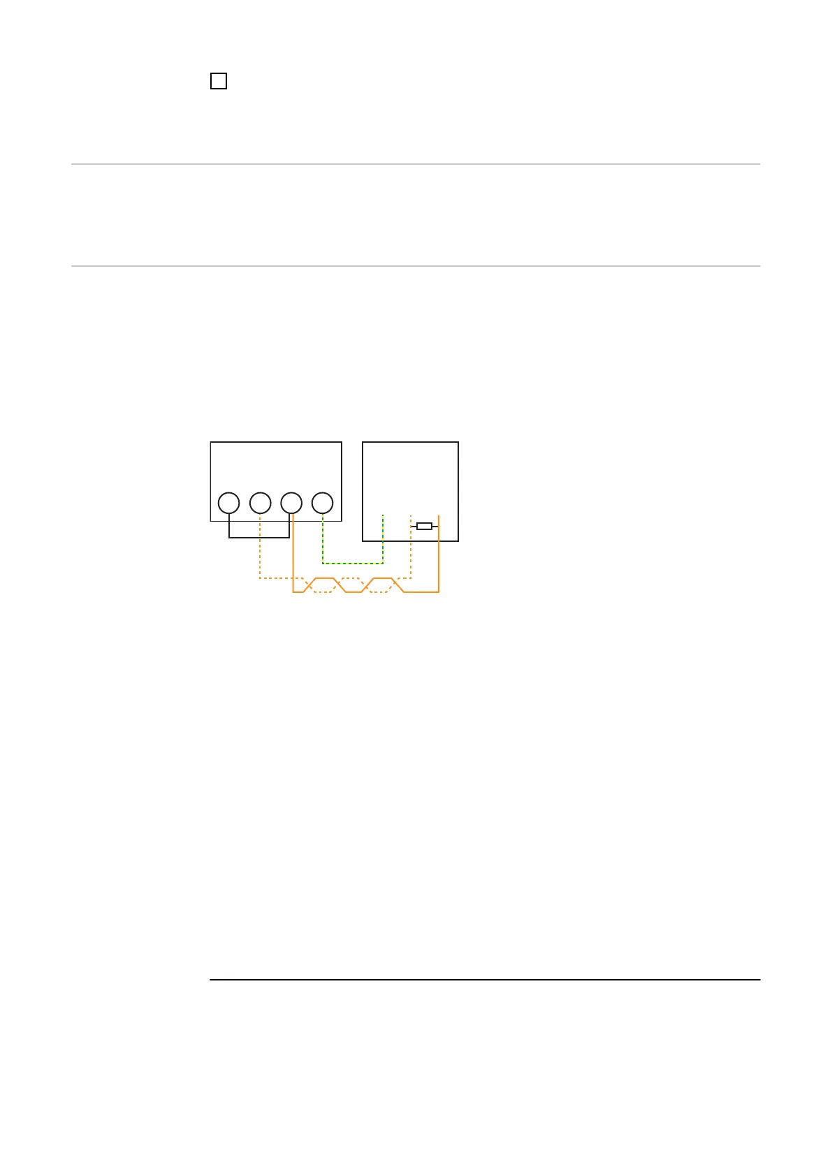
Connecting the
data communica-
tion cable to the
inverter
Connect the data communication connections of the Fronius Smart Meter TS to the Mod-
bus interface of the Fronius inverter using a network cable (CAT5 or higher).
- Connect M+ (Fronius Smart Meter TS) to D+ (Fronius inverter).
- Connect M- (Fronius Smart Meter TS) to D- (Fronius inverter).
- Connect GND (Fronius Smart Meter TS) to - (Fronius inverter).
Several Smart Meters can be installed in the system, see chapter Multi-meter system
on page 25.
Fronius
Inverter
ON
-
*
D+ D-
OUTPUT
RS 485
-
T
D+
M+
M-
D-
GND
* To avoid interference, the terminating resistor must be used (see chapter Terminating
resistors on page 23). This is integrated in the Fronius Smart Meter TS and must be
manufactured with a wire between M and T(T = termination).
ATTENTION! ?
More information on successful commissioning.
Note the following information about connecting the data communication cable to the
inverter.
▶
Use network cables of type CAT5 or higher.
▶
Use a mutual twisted cable pair for corresponding data lines (D+ and D-).
▶
If the data lines are close to the mains cabling, use wires or cables that are designed
for 300 to 600 V (never less than the operating voltage).
▶
Use double-insulated or sheathed data lines when they are close to bare conduct-
ors.
▶
Use shielded twisted pair cables to avoid faults.
▶
Two wires can be installed in each terminal; the wires are twisted first, inserted into
the terminal and tightened.
Note: A loose wire can disable an entire area of the network.
▶
The data communication connections of the Fronius Smart Meter TS are electrically
isolated from hazardous voltages.
22

 Loading...


