maximum expected current per phase should be selected. The closer the expected cur-
rent is to this value, the more precise the measurement will be.
Secondary current
The current transformer must supply alternating current at a nominal current of 1 or 5 A.
The nominal values for the current transformer are listed in the current transformer data
sheet.
Power
The Fronius Smart Meter TS needs 0.5 VA to carry out its measurements. Losses also
occur on the outgoing and return leads. The power of the current converter must be
greater than the sum total of the power of the Fronius Smart Meter TS and the leads.
The higher the power, the better.
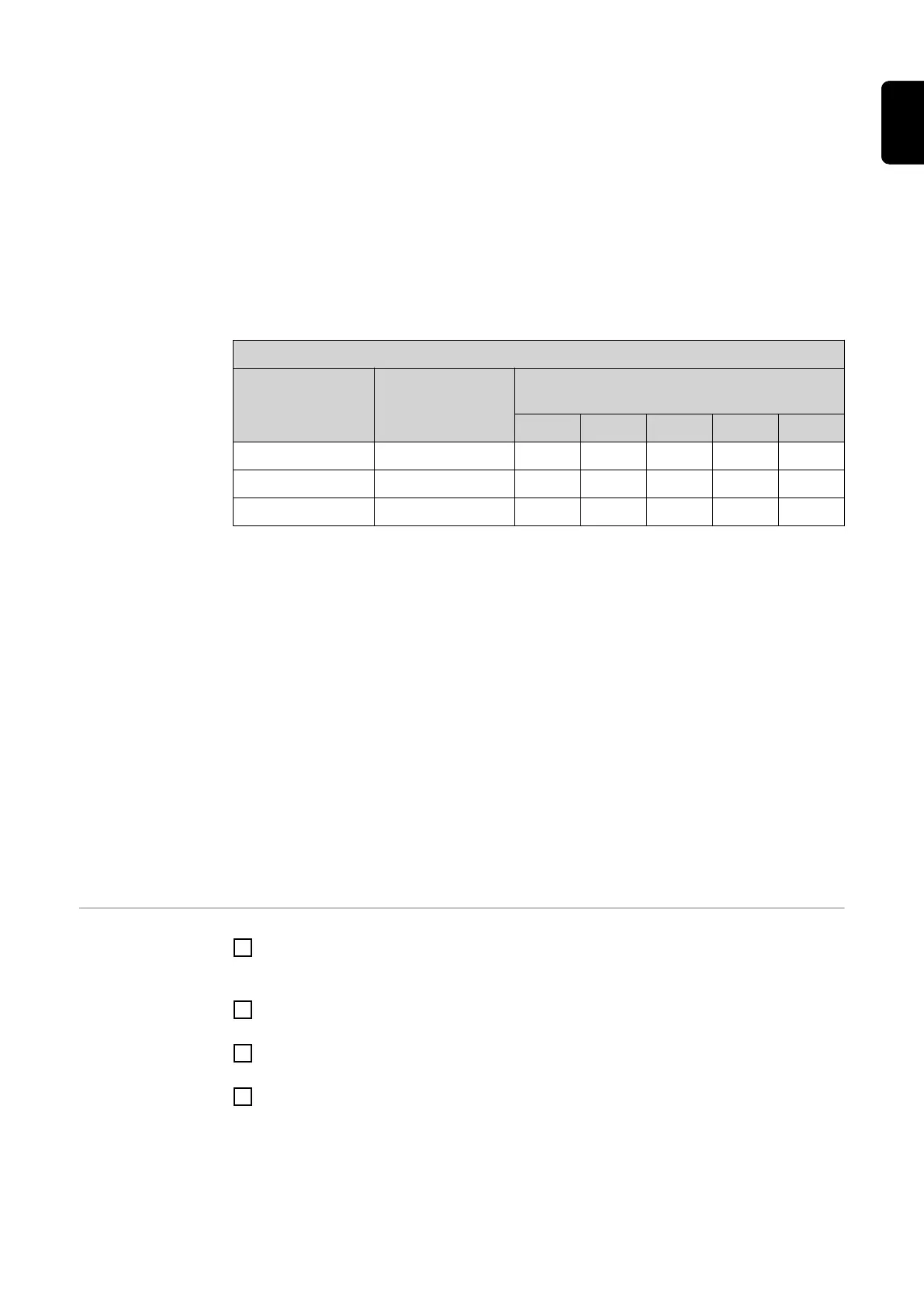
Line resistances at different cross-sections (copper wires)
Secondary cur-
rent
[A]
Cross-section
[mm²]
Line resistances at different lead lengths
(outgoing and return lead)
0.5 m 1.0 m 2.5 m 5 m 10 m
5 1.5 0.3 VA 0.6 VA 1.5 VA 2.9 VA 5.8 VA
5 2.5 0.2 VA 0.4 VA 0.9 VA 1.8 VA 3.6 VA
5 4 - - 0.6 VA 1.1 VA 2.2 VA
Example
The length of the outgoing and return lead (0.5 m each) between the Fronius Smart
Meter TS and the current transformer is a total of 1 m and has a copper cable cross-sec-
tion of 1.5 mm²; the line resistance is therefore 0.6 VA according to the table above. The
self-consumption of the Fronius Smart Meter TS is 0.5 VA.
Line resistance 0.6 VA + self-consumption 0.5 VA = 1.1 VA
→ A current transformer with a rating of 1.5 VA, 5 VA or higher is suitable here.
Accuracy class
Use Class 1 or better (Class 0.5 / 0.2, etc.). Class 1 is equivalent to a deviation of ± 1%
of the secondary current at maximum power.
Mounting
Rigid or hinged
"Rigid" is usually cheaper with better power and accuracy values. Hinged current trans-
formers can be opened for attachment to the conductor. To prevent it being opened inad-
vertently, a plastic cable tie can be secured to the current transformer. Hinged current
transformers can be installed in a system without interrupting the voltage.
Connecting the
current trans-
formers
1
Make sure that the current transformers match the voltage phases. Make sure that
current transformer L1 measures the current on the same phase that is monitored by
voltage input L1. The same applies for phases L2 and L3.
2
Make sure that the current transformers are pointing in the correct direction. Observe
the data sheet for the current transformer.
3
Note down the nominal current of the current transformer for each meter. These val-
ues will be required for setup.
4
Attach the current transformers to the conductor to be measured and connect the
cables of the current transformer to the Fronius Smart Meter TS.
IMPORTANT!
Always switch off the power supply before disconnecting live conductors.
21
EN

 Loading...


